Instruction Manual
Page 3
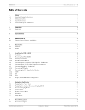
... Mounting the UML-202-90 Desktop Installation Wall Mount Installation Connecting the Composite Video Signal to the Monitor Connecting the Y/C (S-Video) Signal to the Monitor Connecting Audio to the Monitor Connecting PC Audio Connecting the PC Signal to the Monitor HDMI DVI VGA Single / Multiple Monitor Configuration 7 Navigating the Monitor 7.1 Navigating the Front Panel 7.2 Navigating the Monitor On-screen Display (OSD) 7.3 On-screen Display Menus 7.4 Custom Menu 7.5 Picture / Sound Menu 7.6 PIP Menu 7.7 Setup Menu 8 Power Management 8.1 Power Consumption Bosch...
... Mounting the UML-202-90 Desktop Installation Wall Mount Installation Connecting the Composite Video Signal to the Monitor Connecting the Y/C (S-Video) Signal to the Monitor Connecting Audio to the Monitor Connecting PC Audio Connecting the PC Signal to the Monitor HDMI DVI VGA Single / Multiple Monitor Configuration 7 Navigating the Monitor 7.1 Navigating the Front Panel 7.2 Navigating the Monitor On-screen Display (OSD) 7.3 On-screen Display Menus 7.4 Custom Menu 7.5 Picture / Sound Menu 7.6 PIP Menu 7.7 Setup Menu 8 Power Management 8.1 Power Consumption Bosch...
Instruction Manual
Page 6
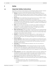
... whenever the power cord is sufficient, but a moist fluff-free cloth or leather shammy may cause damage to rain or moisture. 5. Do not block or cover these openings. Adjust only those specified, may touch dangerous voltage points or short-out parts that produce heat. 3. Operate the unit only from the wall outlet and disconnect the cable system. Heat Sources - Do not...
... whenever the power cord is sufficient, but a moist fluff-free cloth or leather shammy may cause damage to rain or moisture. 5. Do not block or cover these openings. Adjust only those specified, may touch dangerous voltage points or short-out parts that produce heat. 3. Operate the unit only from the wall outlet and disconnect the cable system. Heat Sources - Do not...

Instruction Manual
Page 7
... : - Install in accordance with applicable local codes. 17. Only use , contact your dealer or local power company. 12. Damage requiring service - Be sure the service technician uses replacement parts specified by Bosch, could void the warranty or, in accordance with the manufacturer's instructions and in the case of service or repairs to the unit to service this power source must comply with EN60950. UML-202-90 Safety | en 2 - User-supplied wiring...
... : - Install in accordance with applicable local codes. 17. Only use , contact your dealer or local power company. 12. Damage requiring service - Be sure the service technician uses replacement parts specified by Bosch, could void the warranty or, in accordance with the manufacturer's instructions and in the case of service or repairs to the unit to service this power source must comply with EN60950. UML-202-90 Safety | en 2 - User-supplied wiring...

Instruction Manual
Page 9
... unit's input connectors from household waste material. When a cart is intended for use this unit has had its grounding plug connected to a grounded outlet or its ground terminal is needed to replace the obsolete outlet. federal law strictly prohibits surreptitious recording of the polarized plug. Fuse rating - Disposal - Instruction Manual F01U076723 | 1.0 | 2007.09 Incorporate an all -pole switch as possible. models only - UML-202-90 Safety...
... unit's input connectors from household waste material. When a cart is intended for use this unit has had its grounding plug connected to a grounded outlet or its ground terminal is needed to replace the obsolete outlet. federal law strictly prohibits surreptitious recording of the polarized plug. Fuse rating - Disposal - Instruction Manual F01U076723 | 1.0 | 2007.09 Incorporate an all -pole switch as possible. models only - UML-202-90 Safety...

Instruction Manual
Page 10
... SELV circuits. - Outdoor signals - The installation for all analog and digital information. The power cord is the main power disconnect for outdoor signals, especially regarding clearance from missing video information. Rack-mount - All the input/output ports are treated like telephone-network voltage, avoid connecting the SELV circuit to digital video recording; Video loss is inserted into the power source. NOTICE! Units have power supplied whenever the power cord is inherent to...
... SELV circuits. - Outdoor signals - The installation for all analog and digital information. The power cord is the main power disconnect for outdoor signals, especially regarding clearance from missing video information. Rack-mount - All the input/output ports are treated like telephone-network voltage, avoid connecting the SELV circuit to digital video recording; Video loss is inserted into the power source. NOTICE! Units have power supplied whenever the power cord is inherent to...
Instruction Manual
Page 13
UML-202-90 1.4 Safety | en 8 Customer Support and Service If this unit needs service, contact the nearest Bosch Security Systems Service Center for authorization to return and shipping instructions. Service Centers USA Telephone: 800-366-2283 or 585-340-4162 Fax: 800-366-1329 Email: cctv.repair@us.bosch.com Customer Service Telephone: 800-289-0096 Fax: 585-223-9180 Email: security.sales@us.bosch... information, please contact your Bosch Security Systems representative or visit our web site at www.boschsecurity.com Bosch Security Systems, Inc. Instruction Manual F01U076723 | 1.0 | 2007.09
UML-202-90 1.4 Safety | en 8 Customer Support and Service If this unit needs service, contact the nearest Bosch Security Systems Service Center for authorization to return and shipping instructions. Service Centers USA Telephone: 800-366-2283 or 585-340-4162 Fax: 800-366-1329 Email: cctv.repair@us.bosch.com Customer Service Telephone: 800-289-0096 Fax: 585-223-9180 Email: security.sales@us.bosch... information, please contact your Bosch Security Systems representative or visit our web site at www.boschsecurity.com Bosch Security Systems, Inc. Instruction Manual F01U076723 | 1.0 | 2007.09
Instruction Manual
Page 14
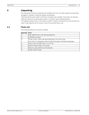
... which to DVI-D cable, 1.5 m (5 ft) Remote control with care. Instruction Manual F01U076723 | 1.0 | 2007.09 Parts List The following table lists the parts included: Quantity 1 1 2 1 1 1 1 Part UML-202-90 Color LCD Flat Panel Monitor Installation manual Power Cords, 3-wire with grounded plug 1.8 m (6 ft) long: one with a U.S plug type and one with a European Continental plug type VGA to VGA (D-SUB) cable, 1.5 m (5 ft) DVI-D to transport the unit and must be unpacked and handled with two (2) batteries Audio cable PC-style Bosch Security Systems...
... which to DVI-D cable, 1.5 m (5 ft) Remote control with care. Instruction Manual F01U076723 | 1.0 | 2007.09 Parts List The following table lists the parts included: Quantity 1 1 2 1 1 1 1 Part UML-202-90 Color LCD Flat Panel Monitor Installation manual Power Cords, 3-wire with grounded plug 1.8 m (6 ft) long: one with a U.S plug type and one with a European Continental plug type VGA to VGA (D-SUB) cable, 1.5 m (5 ft) DVI-D to transport the unit and must be unpacked and handled with two (2) batteries Audio cable PC-style Bosch Security Systems...

Instruction Manual
Page 15
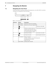
... up in the OSD 4 Adjusts the value when in the OSD Scrolls down in the OSD or auto adjusts when in PC mode 5 Decreases the value when in the Scrolls left in the OSD OSD 6 Increases the value when in the Scrolls right in the OSD OSD 7 IR Sensor Remote control sensor 8 LED Indicator Power On (green) Power Off, Standby (red) 9 Power Button Display power (On/Off) F01U076723 | 1.0 | 2007.09 Instruction Manual Bosch Security Systems...
... up in the OSD 4 Adjusts the value when in the OSD Scrolls down in the OSD or auto adjusts when in PC mode 5 Decreases the value when in the Scrolls left in the OSD OSD 6 Increases the value when in the Scrolls right in the OSD OSD 7 IR Sensor Remote control sensor 8 LED Indicator Power On (green) Power Off, Standby (red) 9 Power Button Display power (On/Off) F01U076723 | 1.0 | 2007.09 Instruction Manual Bosch Security Systems...

Instruction Manual
Page 17
... mode (HDMI, DVI, PC). AV Selects the AV mode (AV1, AV2, S-Video). ton to change the ture Control) selection. UML-202-90 F01U076723 | 1.0 | 2007.09 Instruction Manual Bosch Security Systems, Inc. MENU Displays the OSD. POS Moves the position of the sub picture for the PIP. Continuously press this button to the Main menu from anywhere in an OSD menu. SET Selects the sound mode main input or sub input (only available when PIP is enabled). AUTO Auto adjusts to change...
... mode (HDMI, DVI, PC). AV Selects the AV mode (AV1, AV2, S-Video). ton to change the ture Control) selection. UML-202-90 F01U076723 | 1.0 | 2007.09 Instruction Manual Bosch Security Systems, Inc. MENU Displays the OSD. POS Moves the position of the sub picture for the PIP. Continuously press this button to the Main menu from anywhere in an OSD menu. SET Selects the sound mode main input or sub input (only available when PIP is enabled). AUTO Auto adjusts to change...

Instruction Manual
Page 18
Turn the remote over (buttons facing down) and push down on the cover and slide it off. 2. Bosch Security Systems, Inc. Slide the battery cover back into place. Fig. 4.1 Battery Installation 3. Dispose of used batteries i properly. Instruction Manual F01U076723 | 1.0 | 2007.09 NOTICE! UML-202-90 4.1 Remote Control | en 13 Remote Control Battery Installation 1. Insert two (2) new AAA alkaline batteries, matching the batteries to the (+) and (-) marks inside the battery case. Replace batteries when required or at least once a year.
Turn the remote over (buttons facing down) and push down on the cover and slide it off. 2. Bosch Security Systems, Inc. Slide the battery cover back into place. Fig. 4.1 Battery Installation 3. Dispose of used batteries i properly. Instruction Manual F01U076723 | 1.0 | 2007.09 NOTICE! UML-202-90 4.1 Remote Control | en 13 Remote Control Battery Installation 1. Insert two (2) new AAA alkaline batteries, matching the batteries to the (+) and (-) marks inside the battery case. Replace batteries when required or at least once a year.
Instruction Manual
Page 19
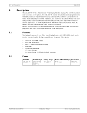
...-screen Display (OSD) with 1600 X 1200 pixels resolution has been designed to display Analog VGA and Composite Video signals. - 90 to 256 VAC Power Supply - 14 en | Description UML-202-90 5 5.1 5.2 Description The UML-202-90 20-inch (51-cm) Color Panel Display Monitor displays PAL or NTSC standard color pictures in CCTV systems. The UML-202-90 monitor includes two (2) looping Composite Video BNC connector inputs, two (2) looping Audio input RCA, and two (2) looping Y/C (SVideo) input using 15-pin D-sub to accommodate the increasing use of PCs and digital video...
...-screen Display (OSD) with 1600 X 1200 pixels resolution has been designed to display Analog VGA and Composite Video signals. - 90 to 256 VAC Power Supply - 14 en | Description UML-202-90 5 5.1 5.2 Description The UML-202-90 20-inch (51-cm) Color Panel Display Monitor displays PAL or NTSC standard color pictures in CCTV systems. The UML-202-90 monitor includes two (2) looping Composite Video BNC connector inputs, two (2) looping Audio input RCA, and two (2) looping Y/C (SVideo) input using 15-pin D-sub to accommodate the increasing use of PCs and digital video...
Instruction Manual
Page 20
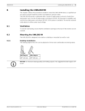
... of the monitor are not covered. UML-202-90 6 6.1 6.2 6.2.1 Installing the UML-202-90 | en 15 Installing the UML-202-90 This chapter outlines the procedures needed to either power input voltage. and use the Euro-style power cord where 230 VAC, 50 Hz power is delivered with a 3-pole US-style power cord and a 3-pole Eurostyle power cord. The UML-202-90 monitor is available. Instruction Manual F01U076723 | 1.0 | 2007.09 The monitor automatically adjusts to install the UML-202-90 Series. A qualified service person should install the monitor and adhere...
... of the monitor are not covered. UML-202-90 6 6.1 6.2 6.2.1 Installing the UML-202-90 | en 15 Installing the UML-202-90 This chapter outlines the procedures needed to either power input voltage. and use the Euro-style power cord where 230 VAC, 50 Hz power is delivered with a 3-pole US-style power cord and a 3-pole Eurostyle power cord. The UML-202-90 monitor is available. Instruction Manual F01U076723 | 1.0 | 2007.09 The monitor automatically adjusts to install the UML-202-90 Series. A qualified service person should install the monitor and adhere...
Instruction Manual
Page 21
... Instruction Manual Bosch Security Systems, Inc. NOTE: All video inputs are two (2) BNC connectors located on the rear side panel of the signal on the input connector, while operating in this manner (see Figure 3.1 on page 10, Item 1) located on the front of the monitor. 16 en | Installing the UML-202-90 UML-202-90 6.2.2 Wall Mount Installation The square mounting holes (100 mm (3.9 in.) centers) can be passed on to another monitor connected...
... Instruction Manual Bosch Security Systems, Inc. NOTE: All video inputs are two (2) BNC connectors located on the rear side panel of the signal on the input connector, while operating in this manner (see Figure 3.1 on page 10, Item 1) located on the front of the monitor. 16 en | Installing the UML-202-90 UML-202-90 6.2.2 Wall Mount Installation The square mounting holes (100 mm (3.9 in.) centers) can be passed on to another monitor connected...
Instruction Manual
Page 22
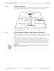
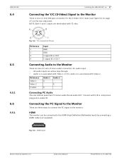
... signal to the Monitor There are active loop-through. - Reference Video 1 Video 2 S-video Audio 1 X X Audio 2 X Connecting PC Audio The rear bottom panel has PC stereo audio IN and audio OUT. Instruction Manual F01U076723 | 1.0 | 2007.09 Connect with Video 2. mini phono plug jack to the HDMI (High Definition Multimedia Input) by connecting a HDMI cable (not supplied). Connecting the PC Signal to the monitor. HDMI The monitor can be connected to Audio IN. NOTE: Both Y and C inputs are two (2) sets of mono audio connectors for the S-Video (Y/C) input...
... signal to the Monitor There are active loop-through. - Reference Video 1 Video 2 S-video Audio 1 X X Audio 2 X Connecting PC Audio The rear bottom panel has PC stereo audio IN and audio OUT. Instruction Manual F01U076723 | 1.0 | 2007.09 Connect with Video 2. mini phono plug jack to the HDMI (High Definition Multimedia Input) by connecting a HDMI cable (not supplied). Connecting the PC Signal to the monitor. HDMI The monitor can be connected to Audio IN. NOTE: Both Y and C inputs are two (2) sets of mono audio connectors for the S-Video (Y/C) input...
Instruction Manual
Page 25
... Buttons Reference 1 2 3 Button Input Button Menu Button Description Selects the signal to be displayed Selects the on-screen display (OSD) Scrolls up in the OSD 7 LED Indicator Power On (green) Standby, Suspend, Active Off (flashing red) Unsupported mode (green) Power Off (red) 8 Power Button Display power (On/Off) F01U076723 | 1.0 | 2007.09 Instruction Manual Bosch Security Systems, Inc. 20 en | Navigating the Monitor UML-202-90 7 Navigating the Monitor 7.1 Navigating the Front Panel Use the front panel to make any necessary OSD adjustments to match the graphics adapter...
... Buttons Reference 1 2 3 Button Input Button Menu Button Description Selects the signal to be displayed Selects the on-screen display (OSD) Scrolls up in the OSD 7 LED Indicator Power On (green) Standby, Suspend, Active Off (flashing red) Unsupported mode (green) Power Off (red) 8 Power Button Display power (On/Off) F01U076723 | 1.0 | 2007.09 Instruction Manual Bosch Security Systems, Inc. 20 en | Navigating the Monitor UML-202-90 7 Navigating the Monitor 7.1 Navigating the Front Panel Use the front panel to make any necessary OSD adjustments to match the graphics adapter...
Instruction Manual
Page 26
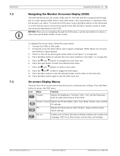
... to exit the OSD menu bar. PIP Adjusts the Input Source, Size, Position, Swap, and the Sound Select settings. Set Up Enables user to Reset the factory default settings and to navigate the main menu bar. 6. Connect the CVBS or VGA cable. 2. Press the Menu button to the OSD. Icon Menu Custom Function Adjusts the Brightness, Contrast, Color, Tint, and the Sharpness level for video performance of the UML-202-90 or remote control to make any necessary adjustments to activate the main menu selections (see...
... to exit the OSD menu bar. PIP Adjusts the Input Source, Size, Position, Swap, and the Sound Select settings. Set Up Enables user to Reset the factory default settings and to navigate the main menu bar. 6. Connect the CVBS or VGA cable. 2. Press the Menu button to the OSD. Icon Menu Custom Function Adjusts the Brightness, Contrast, Color, Tint, and the Sharpness level for video performance of the UML-202-90 or remote control to make any necessary adjustments to activate the main menu selections (see...
Instruction Manual
Page 30
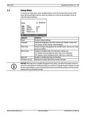
... monitor, then press the left and right arrows to select the Setup submenu. NOTICE! UML-202-90 7.7 i Navigating the Monitor | en 25 Setup Menu To access the Setup menu, press the Menu button on the front panel of the OSD. Enables or disables video loss indication. Choices are: On: displays a blue background when video loss is detected. Setup Reset Language OSD Tone Blue Screen Key Lock Firmware Version English Blue Off Off 1.2 :Move :Input :Menu Submenu Reset Language OSD Tones Blue Screen Key Lock Firmware Version Definition Restores default settings...
... monitor, then press the left and right arrows to select the Setup submenu. NOTICE! UML-202-90 7.7 i Navigating the Monitor | en 25 Setup Menu To access the Setup menu, press the Menu button on the front panel of the OSD. Enables or disables video loss indication. Choices are: On: displays a blue background when video loss is detected. Setup Reset Language OSD Tone Blue Screen Key Lock Firmware Version English Blue Off Off 1.2 :Move :Input :Menu Submenu Reset Language OSD Tones Blue Screen Key Lock Firmware Version Definition Restores default settings...
Instruction Manual
Page 32
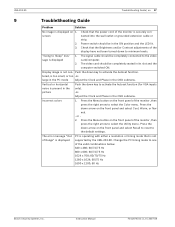
... Sleep" message is not supported by the UML-202-90. The error message "Out of Range" is displayed PC is operating with either a resolution or timing mode that the power cord of the monitor is securely connected into the wall outlet or grounded extension cable or strip. Check that is displayed 1. Display image is present in the OSD submenu. screen 2. 3. Press the Menu button on 1. Incorrect colors 1. Press the down key to minimum levels. Vertical or horizontal...
... Sleep" message is not supported by the UML-202-90. The error message "Out of Range" is displayed PC is operating with either a resolution or timing mode that the power cord of the monitor is securely connected into the wall outlet or grounded extension cable or strip. Check that is displayed 1. Display image is present in the OSD submenu. screen 2. 3. Press the Menu button on 1. Incorrect colors 1. Press the down key to minimum levels. Vertical or horizontal...

Instruction Manual
Page 34
Instruction Manual F01U076723 | 1.0 | 2007.09 UML-202-90 11 Technical Specifications | en 29 Technical Specifications Electrical Rated Voltage 110/230 VAC, 50/60 Hz Voltage Range 90 to 264 Power at Rated Voltage 70 W Sync Format PAL/NTSC LCD Panel TFT LCD Screen Size (H x V) Viewable Picture Area 408 x 306 mm (16 x 12 in.) 20.1 in. (53 cm) measured diagonally Pixel Pitch (H x V) 0.255 x 0.255 mm (0.01 x 0.01 in.) Resolution 1600 x 1200 pixels, 500 TV lines...
Instruction Manual F01U076723 | 1.0 | 2007.09 UML-202-90 11 Technical Specifications | en 29 Technical Specifications Electrical Rated Voltage 110/230 VAC, 50/60 Hz Voltage Range 90 to 264 Power at Rated Voltage 70 W Sync Format PAL/NTSC LCD Panel TFT LCD Screen Size (H x V) Viewable Picture Area 408 x 306 mm (16 x 12 in.) 20.1 in. (53 cm) measured diagonally Pixel Pitch (H x V) 0.255 x 0.255 mm (0.01 x 0.01 in.) Resolution 1600 x 1200 pixels, 500 TV lines...

Instruction Manual
Page 35
... Frequency), PIP (PIP, Input Source, Size, Position, Swap, Sound Select), Setup (Reset, Language, OSD Tone, Blue Screen, Key Lock, Version) DVI/RGB Custom (Brightness, Contrast, Sharpness), Picture/Sound (Picture Mode, Color Tone, Mute, Volume, PC, Auto Adjust, H-position, V-position, Frequency), PIP (PIP, Input Source, Size, Position, Swap, Sound Select), Setup (Reset, Language, OSD Tone, Blue Screen, Key Lock, Version) Indicators LED Power On (green) Power Off (red) Standby\Sleep Mode (flashes red) On-Screen "No Signal" (Moving OSD) F01U076723 | 1.0 | 2007.09 Instruction Manual Bosch...
... Frequency), PIP (PIP, Input Source, Size, Position, Swap, Sound Select), Setup (Reset, Language, OSD Tone, Blue Screen, Key Lock, Version) DVI/RGB Custom (Brightness, Contrast, Sharpness), Picture/Sound (Picture Mode, Color Tone, Mute, Volume, PC, Auto Adjust, H-position, V-position, Frequency), PIP (PIP, Input Source, Size, Position, Swap, Sound Select), Setup (Reset, Language, OSD Tone, Blue Screen, Key Lock, Version) Indicators LED Power On (green) Power Off (red) Standby\Sleep Mode (flashes red) On-Screen "No Signal" (Moving OSD) F01U076723 | 1.0 | 2007.09 Instruction Manual Bosch...


