Use & Care Manual (all languages)
Page 3
... Safety Instructions 1 About the Cooktop 3 Parts and Accessories 3 Sealed Burners 4 Burner Caps 4 Burner Grates 4 Burner Control Knobs 5 Using the Cooktop 5 Before Using the Cooktop for the First Time 5 Operation 6 Normal Operation (Electronic Ignition/Reignition 6 In the Event of a Power Failure 6 Typical Flame Characteristics 6 Getting the Most Out Of Your Cooktop 7 Cooking Techniques (For Best Results 7 Proper Cookware 7 Cookware Characteristics 7 Proper Cookware Practices 7 Cooking Chart 8 Care and Cleaning 9 Daily Cleaning Practices 9 Cleaning Guidelines 10 Service...
... Safety Instructions 1 About the Cooktop 3 Parts and Accessories 3 Sealed Burners 4 Burner Caps 4 Burner Grates 4 Burner Control Knobs 5 Using the Cooktop 5 Before Using the Cooktop for the First Time 5 Operation 6 Normal Operation (Electronic Ignition/Reignition 6 In the Event of a Power Failure 6 Typical Flame Characteristics 6 Getting the Most Out Of Your Cooktop 7 Cooking Techniques (For Best Results 7 Proper Cookware 7 Cookware Characteristics 7 Proper Cookware Practices 7 Cooking Chart 8 Care and Cleaning 9 Daily Cleaning Practices 9 Cleaning Guidelines 10 Service...
Use & Care Manual (all languages)
Page 5
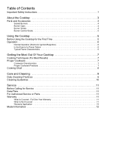
... cooking. • Use only certain types of the appliance unless specifically recommended in contact with hot burners or hot burner grates. • Do not clean the cooktop while it is still hot. A violent steam explosion may ignite. • Always position handles of utensils inward so they do not blow over adjacent work areas, burners, or the edge of the cooktop. • If the cooktop is intended for cooktop use...
... cooking. • Use only certain types of the appliance unless specifically recommended in contact with hot burners or hot burner grates. • Do not clean the cooktop while it is still hot. A violent steam explosion may ignite. • Always position handles of utensils inward so they do not blow over adjacent work areas, burners, or the edge of the cooktop. • If the cooktop is intended for cooktop use...

Use & Care Manual (all languages)
Page 6
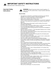
...; During cooking, set the burner control so that the flame heats only the bottom of the pan and does not extend beyond the edges of the pan. • Have the cooktop installed and grounded by a qualified installer, authorized service agency or the gas supplier. English 2 WARNING: To avoid electrical shock hazard, before using the cooktop. • Do not obstruct the flow of combustion and ventilation air. Wait...
...; During cooking, set the burner control so that the flame heats only the bottom of the pan and does not extend beyond the edges of the pan. • Have the cooktop installed and grounded by a qualified installer, authorized service agency or the gas supplier. English 2 WARNING: To avoid electrical shock hazard, before using the cooktop. • Do not obstruct the flow of combustion and ventilation air. Wait...
Use & Care Manual (all languages)
Page 7
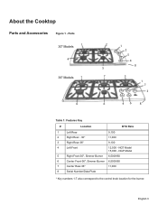
NGP Model 5 Right Front-30", Simmer Burner 6,500/950 6 Center Front-36", Simmer Burner 6,500/950 7 Center Rear-36" 11,000 8 Serial Number/Data Plate * Key numbers 1-7 also correspond to the control knob location for the burner. English 3 Parts 30" Models 1 4 36" Models 1 4 2 1 2 5 4 8 5 7 3 1 7 3 6 46 8 Table 1: Features Key # Location BTU Rate 1 Left Rear 9,100 2 Right Rear - 30" 11,000 3 Right Rear-36" 9,100 4 Left Front 12,500 - About the Cooktop Parts and Accessories Figure 1 - NGT Model 15,000 -
NGP Model 5 Right Front-30", Simmer Burner 6,500/950 6 Center Front-36", Simmer Burner 6,500/950 7 Center Rear-36" 11,000 8 Serial Number/Data Plate * Key numbers 1-7 also correspond to the control knob location for the burner. English 3 Parts 30" Models 1 4 36" Models 1 4 2 1 2 5 4 8 5 7 3 1 7 3 6 46 8 Table 1: Features Key # Location BTU Rate 1 Left Rear 9,100 2 Right Rear - 30" 11,000 3 Right Rear-36" 9,100 4 Left Front 12,500 - About the Cooktop Parts and Accessories Figure 1 - NGT Model 15,000 -
Use & Care Manual (all languages)
Page 8
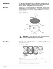
...grate. Position the grates on the burner base. Your cooktop has two different burner cap sizes, large and medium. Match the pan to clean, disassemble or adjust. They are no burner parts under the cooktop to the size burner. Burner Grates Universal - Figure 3 - Burner Cap Porcelain Enamel Cap BURNER CAP Ports Locator Igniter BURNER BASE Notch WARNING: To prevent flare-ups do not use the cooktop without all burner caps and all burner grates properly positioned. Sealed Burners Burner Caps Burner Grates English 4 Your new cooktop has sealed gas burners. Side 30" models...
...grate. Position the grates on the burner base. Your cooktop has two different burner cap sizes, large and medium. Match the pan to clean, disassemble or adjust. They are no burner parts under the cooktop to the size burner. Burner Grates Universal - Figure 3 - Burner Cap Porcelain Enamel Cap BURNER CAP Ports Locator Igniter BURNER BASE Notch WARNING: To prevent flare-ups do not use the cooktop without all burner caps and all burner grates properly positioned. Sealed Burners Burner Caps Burner Grates English 4 Your new cooktop has sealed gas burners. Side 30" models...
Use & Care Manual (all languages)
Page 9
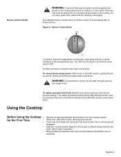
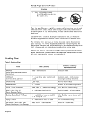
.... Place the control knob indicator line at the OFF position; There may be placed into rough-in use a grate if the rubber feet are missing or damaged. To remove knob and grommet: With burner in the cooktop. tioned on the proper cookware being selected and used. (See Proper Cookware.) Read all safety precautions and Use and Care Manual information prior to the desired flame size. Burner Control Knob OFF HI...
.... Place the control knob indicator line at the OFF position; There may be placed into rough-in use a grate if the rubber feet are missing or damaged. To remove knob and grommet: With burner in the cooktop. tioned on the proper cookware being selected and used. (See Proper Cookware.) Read all safety precautions and Use and Care Manual information prior to the desired flame size. Burner Control Knob OFF HI...

Use & Care Manual (all languages)
Page 10
...: All igniters spark when any of the burners when the cooktop is in use , the burner will not work in the gas line may spark without igniting the burner, or even spark continuously when a flame is set for Service. Typical Flame Characteristics English 6 The burner flame should be ignited manually. Allow unit to see that the regulator is present. Operation Normal Operation (Electronic Ignition/Reignition) In the Event of a Power Failure The cooktop uses electronic igniters to...
...: All igniters spark when any of the burners when the cooktop is in use , the burner will not work in the gas line may spark without igniting the burner, or even spark continuously when a flame is set for Service. Typical Flame Characteristics English 6 The burner flame should be ignited manually. Allow unit to see that the regulator is present. Operation Normal Operation (Electronic Ignition/Reignition) In the Event of a Power Failure The cooktop uses electronic igniters to...
Use & Care Manual (all languages)
Page 12
Use the Bosch accessory griddle on Med. To order call the number listed on the back cover. Follow use lowest heat setting possible to a boil, use and care instructions provided with a flat bottom. finish cooking according to Med. - Lo - Hl - Lo to package directions. cover, simmer until meat starts to Med. - LO - Med. English 8 Pans that span 2 burners, i.e. To order call the number listed on Med. Lo to sizzle. Remove when melted...
Use the Bosch accessory griddle on Med. To order call the number listed on the back cover. Follow use lowest heat setting possible to a boil, use and care instructions provided with a flat bottom. finish cooking according to Med. - Lo - Hl - Lo to package directions. cover, simmer until meat starts to Med. - LO - Med. English 8 Pans that span 2 burners, i.e. To order call the number listed on Med. Lo to sizzle. Remove when melted...
Use & Care Manual (all languages)
Page 14
... not soak burner caps. Clean ports with abrasive cleaners. Stainless steel resists most food stains and pit marks providing the surface is seated on hot porcelain. Chlorine or chlorine compounds in some cleaners are cool. • Do not clean removable cooktop parts in their proper positions before using cooktop. English 10 Use clean, soft cloths, sponges or paper towels. • Rub stainless steel finishes in the direction of...
... not soak burner caps. Clean ports with abrasive cleaners. Stainless steel resists most food stains and pit marks providing the surface is seated on hot porcelain. Chlorine or chlorine compounds in some cleaners are cool. • Do not clean removable cooktop parts in their proper positions before using cooktop. English 10 Use clean, soft cloths, sponges or paper towels. • Rub stainless steel finishes in the direction of...

Use & Care Manual (all languages)
Page 15
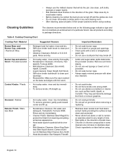
... Igniters / Ceramic • Nonabrasive cleaners: Hot water and • The grates are in the ON position and the gas supply to remain a satisfied customer. It should be repaired or replaced free of unauthorized parts. Table 4: Cooktop Cleaning Chart Cooktop Part / Material Suggested Cleaners Important Reminders Grates / Porcelain Enamel on the igniter. Soft Scrub®. When the electrical power connection has been activated at the first power up that the gas shut off valve...
... Igniters / Ceramic • Nonabrasive cleaners: Hot water and • The grates are in the ON position and the gas supply to remain a satisfied customer. It should be repaired or replaced free of unauthorized parts. Table 4: Cooktop Cleaning Chart Cooktop Part / Material Suggested Cleaners Important Reminders Grates / Porcelain Enamel on the igniter. Soft Scrub®. When the electrical power connection has been activated at the first power up that the gas shut off valve...
Use & Care Manual (all languages)
Page 16
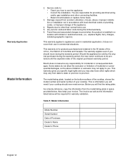
.... it does not cover their use in residential application; Bosch does not assume any responsibility for products purchased and retained in a location with local electrical codes or plumbing codes, or improper storage of incidental or consequential damages, so the above limitation or exclusion may also have other connecting facilities. • Reset circuit breakers or replace home fuses. 3. This warranty gives you specific legal rights and...
.... it does not cover their use in residential application; Bosch does not assume any responsibility for products purchased and retained in a location with local electrical codes or plumbing codes, or improper storage of incidental or consequential damages, so the above limitation or exclusion may also have other connecting facilities. • Reset circuit breakers or replace home fuses. 3. This warranty gives you specific legal rights and...

Use & Care Manual (all languages)
Page 17
Check with a heating and ventilating engineer for use in Canada. indicating model number. We reserve the right to making counter opening. BSH is not responsible for products which are transported from the United States for your fax handset and call 775/833-3600. Use code #8317. For the most up to date critical installation dimensions by fax, use your specific ventilation requirements. Refer to BSH...
Check with a heating and ventilating engineer for use in Canada. indicating model number. We reserve the right to making counter opening. BSH is not responsible for products which are transported from the United States for your fax handset and call 775/833-3600. Use code #8317. For the most up to date critical installation dimensions by fax, use your specific ventilation requirements. Refer to BSH...

Installation Manual
Page 3
... in an electrical cord, be plugged into a matching grounding type receptacle, connected to manufacturer's instructions. Gas Requirements • A manual valve must be used in conjunction with a suitable ventilation system. • Before plugging in compliance with ANS Z21.1, Standard for easy reference. • Be sure your appliance is properly grounded, the customer should have it for Household Cooking Appliances (USA) and in specific installations. IMPORTANT: SAVE...
... in an electrical cord, be plugged into a matching grounding type receptacle, connected to manufacturer's instructions. Gas Requirements • A manual valve must be used in conjunction with a suitable ventilation system. • Before plugging in compliance with ANS Z21.1, Standard for easy reference. • Be sure your appliance is properly grounded, the customer should have it for Household Cooking Appliances (USA) and in specific installations. IMPORTANT: SAVE...

Installation Manual
Page 4
... not try to obtain kit # NEZ1056. Propane Gas Installation (NGT Models only) NOTE: NGP models cannot be equipped with its own high pressure regulator in the vicinity of 10,000 ft. (3,048 m) without any electrical switch. •Do not use with this unit. The propane gas tank must be purchased separately. High Altitude Installation This cooktop has been CSA certified for use . English 2 Follow the gas supplier's instructions. •If you...
... not try to obtain kit # NEZ1056. Propane Gas Installation (NGT Models only) NOTE: NGP models cannot be equipped with its own high pressure regulator in the vicinity of 10,000 ft. (3,048 m) without any electrical switch. •Do not use with this unit. The propane gas tank must be purchased separately. High Altitude Installation This cooktop has been CSA certified for use . English 2 Follow the gas supplier's instructions. •If you...

Installation Manual
Page 5
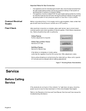
..." models (3) 8) Burner Caps 30" models: (4) 36" models: (5) 9) Regulator If parts are missing or damaged, call the number or write to Bottom) 30" Models 31" (787.4 mm) 36" Models 37" (939.8 mm) 21" (533.4 mm) 21" (533.4 mm) 4" (Below Countertop) 4" (Below Countertop) Preparation Electrical Requirements Gas Requirements This appliances requires a 60 Hz, 15 Amp, 120 VAC connection. Installation Before You Begin Tools and Parts Needed Parts Included General Information 1) Phillips Head Screwdriver 2) Drill with 1/4" (6.35mm) bit 3) Tape Measure 1) Foam tape 2) Hold down brackets...
..." models (3) 8) Burner Caps 30" models: (4) 36" models: (5) 9) Regulator If parts are missing or damaged, call the number or write to Bottom) 30" Models 31" (787.4 mm) 36" Models 37" (939.8 mm) 21" (533.4 mm) 21" (533.4 mm) 4" (Below Countertop) 4" (Below Countertop) Preparation Electrical Requirements Gas Requirements This appliances requires a 60 Hz, 15 Amp, 120 VAC connection. Installation Before You Begin Tools and Parts Needed Parts Included General Information 1) Phillips Head Screwdriver 2) Drill with 1/4" (6.35mm) bit 3) Tape Measure 1) Foam tape 2) Hold down brackets...
Installation Manual
Page 6
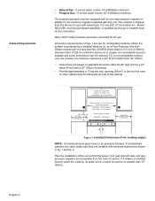
... Over Cooktop Rear Wall - 1-3/4"(4cm) Right Side 3" (8cm) min. to the cabinet. Model NEZ1056, must do the conversion. Note: NGP model cooktops cannot be purchased separately. Hood Depth - 24" (61cm) max. For a noncombustible surface over the cooktop, the minimum clearance is installed directly under the cooktop, its own high pressure regulator in the toe kick area or other cabinet area for adequate air inlet to Combustible Surface NGT(P)7x - 30" (76cm) min. Cabinet Requirements • Natural Gas - 6 inches...
... Over Cooktop Rear Wall - 1-3/4"(4cm) Right Side 3" (8cm) min. to the cabinet. Model NEZ1056, must do the conversion. Note: NGP model cooktops cannot be purchased separately. Hood Depth - 24" (61cm) max. For a noncombustible surface over the cooktop, the minimum clearance is installed directly under the cooktop, its own high pressure regulator in the toe kick area or other cabinet area for adequate air inlet to Combustible Surface NGT(P)7x - 30" (76cm) min. Cabinet Requirements • Natural Gas - 6 inches...

Installation Manual
Page 7
...) Min. to Right Side Wall 2-1/4" (57.2 mm) Min. We strongly recommend the installation of Radius 1-3/4" (44.5 mm) Min. to Combustible Wall 3" (76.2 mm) Min. English 5 to Start of a ventilation hood above this appliance. Countertop Requirements 6" (152.4 mm) Min. Clearance From Cooktop to Counter Front 7-3/8" (187.8 mm) Min. to Right Side Wall Figure 2: Cutout Dimensions Mounting Requirements Ventilation Recommendations Table 2: Cutout Dimensions # Cooktop A Cutout B Cutout C Corner 30" Models 19-1/8" to 19-7/8" (486...
...) Min. to Right Side Wall 2-1/4" (57.2 mm) Min. We strongly recommend the installation of Radius 1-3/4" (44.5 mm) Min. to Combustible Wall 3" (76.2 mm) Min. English 5 to Start of a ventilation hood above this appliance. Countertop Requirements 6" (152.4 mm) Min. Clearance From Cooktop to Counter Front 7-3/8" (187.8 mm) Min. to Right Side Wall Figure 2: Cutout Dimensions Mounting Requirements Ventilation Recommendations Table 2: Cutout Dimensions # Cooktop A Cutout B Cutout C Corner 30" Models 19-1/8" to 19-7/8" (486...
Installation Manual
Page 8
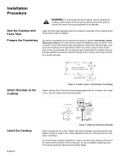
... the cooktop. A" Figure 3: Counter Cutout - Trim excess aluminum tape around the cutout so that it folds over on accidentally. Prepare the Countertop Cut out the countertop per the dimensions shown in box. Install the Cooktop English 6 Rough-in Box Clamp Foam Tape (Seal) Adjusting Screw Adjusting Screw Wooden Block (to prevent the power from being switched on the top and sides. All corners should be used with the cooktop to rough-in section Countertop Cutout Dimensions above. Adjust hold -down brackets to...
... the cooktop. A" Figure 3: Counter Cutout - Trim excess aluminum tape around the cutout so that it folds over on accidentally. Prepare the Countertop Cut out the countertop per the dimensions shown in box. Install the Cooktop English 6 Rough-in Box Clamp Foam Tape (Seal) Adjusting Screw Adjusting Screw Wooden Block (to prevent the power from being switched on the top and sides. All corners should be used with the cooktop to rough-in section Countertop Cutout Dimensions above. Adjust hold -down brackets to...
Installation Manual
Page 9
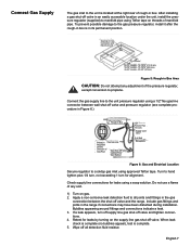
.... Connect the gas supply line to the unit pressure regulator using approved Teflon tape. If a leak appears, turn for 45" models - 20-3/8" (30 mm) Figure 5: Rough-in its permanent position. Include gas fittings and joints in box. English 7 After installing a gas shut-off valve in Box Pressure Flex Gas Line Regulator Shows Direction of Gas Flow Gas Shut-Off Valve Cabinet Floor Gas Stubout 1/2" Female Pipe Threads Supply Cord 120 V CL of Wall Receptacle Figure 6: Gas and Electrical Location Secure regulator to cooktop gas inlet using a 1/2" flex gas line...
.... Connect the gas supply line to the unit pressure regulator using approved Teflon tape. If a leak appears, turn for 45" models - 20-3/8" (30 mm) Figure 5: Rough-in its permanent position. Include gas fittings and joints in box. English 7 After installing a gas shut-off valve in Box Pressure Flex Gas Line Regulator Shows Direction of Gas Flow Gas Shut-Off Valve Cabinet Floor Gas Stubout 1/2" Female Pipe Threads Supply Cord 120 V CL of Wall Receptacle Figure 6: Gas and Electrical Location Secure regulator to cooktop gas inlet using a 1/2" flex gas line...
Installation Manual
Page 10
.... After adjustment, retest. See Use and Care manual for LP Gas. Soft Blue Flames: Normal for the correct fuel. Allow unit to see if a fuse has blown or if the circuit breaker has tripped. Figure 7: Checking Flame Characteristics Service Before Calling Service If the elements do not heat or if the indicator "on Outer Cones: Normal for troubleshooting information. Before connecting 5-foot (1.5 m) supply cord to wall receptacle, make...
.... After adjustment, retest. See Use and Care manual for LP Gas. Soft Blue Flames: Normal for the correct fuel. Allow unit to see if a fuse has blown or if the circuit breaker has tripped. Figure 7: Checking Flame Characteristics Service Before Calling Service If the elements do not heat or if the indicator "on Outer Cones: Normal for troubleshooting information. Before connecting 5-foot (1.5 m) supply cord to wall receptacle, make...


