Instruction Manual
Page 1
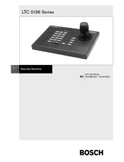
LTC 5136 Series Instruction Manual EN AutoDome® Controller
LTC 5136 Series Instruction Manual EN AutoDome® Controller
Instruction Manual
Page 2
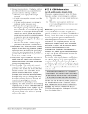
... outlet. Do not defeat the safety purpose of the polarized plug. Power Lines - Object and Liquid Entry - Do not attempt to the operating instructions. 11. LTC 5136 Series | Instruction Manual | Important Safeguards EN | 2 Important Safeguards 1. Heed Warnings - All operating and use attachments not recommended by the manufacturer. Unplug the unit from battery ...in a risk of CATV systems. 14. Servicing - Refer all servicing to the National Electrical Code Article 820 regarding installation of fire or electric shock. 15. Bosch Security Systems | 04 September 2003
... outlet. Do not defeat the safety purpose of the polarized plug. Power Lines - Object and Liquid Entry - Do not attempt to the operating instructions. 11. LTC 5136 Series | Instruction Manual | Important Safeguards EN | 2 Important Safeguards 1. Heed Warnings - All operating and use attachments not recommended by the manufacturer. Unplug the unit from battery ...in a risk of CATV systems. 14. Servicing - Refer all servicing to the National Electrical Code Article 820 regarding installation of fire or electric shock. 15. Bosch Security Systems | 04 September 2003
Instruction Manual
Page 3
... covered by the operating instructions, as the original part. Government Printing Office, Washington, DC 20402, Stock No. 004-000-00345-4. LTC 5136 Series | Instruction Manual | FCC Information EN | 3 17. Replacement Parts - Unauthorized substitutions may cause undesired operation. Upon completion of this...must accept any service or repairs to this equipment in a residential area is left unattended and unused for corrective action. Bosch Security Systems | 04 September 2003 Adjust only those controls that may result in a commercial environment. Operation is in accordance...
... covered by the operating instructions, as the original part. Government Printing Office, Washington, DC 20402, Stock No. 004-000-00345-4. LTC 5136 Series | Instruction Manual | FCC Information EN | 3 17. Replacement Parts - Unauthorized substitutions may cause undesired operation. Upon completion of this...must accept any service or repairs to this equipment in a residential area is left unattended and unused for corrective action. Bosch Security Systems | 04 September 2003 Adjust only those controls that may result in a commercial environment. Operation is in accordance...
Instruction Manual
Page 8
LTC 5136 Series | Instruction Manual | Contents EN | 8 Table of Contents Important Safeguards 2 FCC Information 2 1 UNPACKING 9 2 SERVICE 9 3 DESCRIPTION 9 3.1 Power 9 4 INSTALLATION 10 4.1 General 10 4.2 Installation using Biphase Code 10 4.3 Installation ... Camera or Receiver/Driver Site Configuration 13 5 SETTING FAST ADDRESS FEATURE 13 6 CONTROLLER OPERATION 14 6.1 Controls/Indicators 14 7 TECHNICAL REFERENCE 16 8 DATA CONVERTER PINOUTS 19 Bosch Security Systems | 04 September 2003
LTC 5136 Series | Instruction Manual | Contents EN | 8 Table of Contents Important Safeguards 2 FCC Information 2 1 UNPACKING 9 2 SERVICE 9 3 DESCRIPTION 9 3.1 Power 9 4 INSTALLATION 10 4.1 General 10 4.2 Installation using Biphase Code 10 4.3 Installation ... Camera or Receiver/Driver Site Configuration 13 5 SETTING FAST ADDRESS FEATURE 13 6 CONTROLLER OPERATION 14 6.1 Controls/Indicators 14 7 TECHNICAL REFERENCE 16 8 DATA CONVERTER PINOUTS 19 Bosch Security Systems | 04 September 2003
Instruction Manual
Page 9
..., replace it for the following items: • LTC 5136/61 or LTC 5136/51 Desktop Controller. • Interface unit. • Power supply. • Power supply cable. • One (1) 3 m (10 ft) cable with the Bosch AutoDome Series cameras. The shipping carton is connected to return and shipping instructions. 3 DESCRIPTION The LTC 5136 Series Controllers are designed for authorization to a single AutoDome...
..., replace it for the following items: • LTC 5136/61 or LTC 5136/51 Desktop Controller. • Interface unit. • Power supply. • Power supply cable. • One (1) 3 m (10 ft) cable with the Bosch AutoDome Series cameras. The shipping carton is connected to return and shipping instructions. 3 DESCRIPTION The LTC 5136 Series Controllers are designed for authorization to a single AutoDome...
Instruction Manual
Page 10
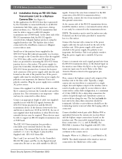
... to connect the RS-232 wires TX and GND from the Controller has successfully been converted into the jack located on the interface unit. LTC 5136 Series | Instruction Manual | Installation EN | 10 4 INSTALLATION 4.1 General The desktop Controller unit should be terminated. The interface unit also provides ... to indicate that supplied 3 m (10 ft) data cable can be using the supplied interface unit. Bosch Security Systems | 04 September 2003 For RS-232 applications, an LTC 8557 Series Remote Keyboard Hookup Kit should be used . One of 1.5 km (5000 ft). If the power supply...
... to connect the RS-232 wires TX and GND from the Controller has successfully been converted into the jack located on the interface unit. LTC 5136 Series | Instruction Manual | Installation EN | 10 4 INSTALLATION 4.1 General The desktop Controller unit should be terminated. The interface unit also provides ... to indicate that supplied 3 m (10 ft) data cable can be using the supplied interface unit. Bosch Security Systems | 04 September 2003 For RS-232 applications, an LTC 8557 Series Remote Keyboard Hookup Kit should be used . One of 1.5 km (5000 ft). If the power supply...
Instruction Manual
Page 11
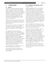
... the AutoDome camera or receiver/ driver. the Interface Unit is the Signal Ground connection. Bosch Security Systems | 04 September 2003 LTC 5136 Series | Instruction Manual | Installation EN | 11 Pin 1 Pin 6 Figure 1 Interface Unit Supplied with RS-232 signals, between the LTC 8557 Series junction box, and the camera site receiver/driver location. polarity sensitive. If desired...
... the AutoDome camera or receiver/ driver. the Interface Unit is the Signal Ground connection. Bosch Security Systems | 04 September 2003 LTC 5136 Series | Instruction Manual | Installation EN | 11 Pin 1 Pin 6 Figure 1 Interface Unit Supplied with RS-232 signals, between the LTC 8557 Series junction box, and the camera site receiver/driver location. polarity sensitive. If desired...
Instruction Manual
Page 12
... a suitable AC power source. Connect the supplied 3 m (10 ft) data cable with LTC 5136. Connect shielded twisted pair cable (Belden 8760 or equivalent) between the LTC 8557 Series junction box and the RS-232 transmission device. See FIGURE 1, Interface Unit Supplied with two RJ...the four holes provided to mount the box to handle up phone modems, etc.). Refer to the data ground connection. Bosch Security Systems | 04 September 2003 LTC 5136 Series | Instruction Manual | Installation EN | 12 4.4 Installation Using an RS-232 Data Transmission Link to a Biphase Camera Site...
... a suitable AC power source. Connect the supplied 3 m (10 ft) data cable with LTC 5136. Connect shielded twisted pair cable (Belden 8760 or equivalent) between the LTC 8557 Series junction box and the RS-232 transmission device. See FIGURE 1, Interface Unit Supplied with two RJ...the four holes provided to mount the box to handle up phone modems, etc.). Refer to the data ground connection. Bosch Security Systems | 04 September 2003 LTC 5136 Series | Instruction Manual | Installation EN | 12 4.4 Installation Using an RS-232 Data Transmission Link to a Biphase Camera Site...
Instruction Manual
Page 13
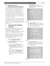
...ENTER). 2. At this point, any camera whose ID does not begin with the AutoDome Camera or Allegiant Series Receiver/Driver unit to connect the data cable to program. Bosch Security Systems | 04 September 2003 Figure FA3 The screen shown in the Fast Addressing mode. • If... unit. Press ON-26-ENTER. Call up the camera to the screen you are NOT connected to change or disable a Fast Address. LTC 5136 Series | Instruction Manual | Setting Fast Addess Feature EN | 13 4.5 AutoDome Camera or Receiver/Driver Site Configuration Follow the standard installation instructions provided...
...ENTER). 2. At this point, any camera whose ID does not begin with the AutoDome Camera or Allegiant Series Receiver/Driver unit to connect the data cable to program. Bosch Security Systems | 04 September 2003 Figure FA3 The screen shown in the Fast Addressing mode. • If... unit. Press ON-26-ENTER. Call up the camera to the screen you are NOT connected to change or disable a Fast Address. LTC 5136 Series | Instruction Manual | Setting Fast Addess Feature EN | 13 4.5 AutoDome Camera or Receiver/Driver Site Configuration Follow the standard installation instructions provided...
Instruction Manual
Page 14
...: Press USER-1-ENTER to store the position. Press ON-1-ENTER and the address is used Bosch Security Systems | 04 September 2003 This command causes all AutoDome cameras and Allegiant Series Receiver/ Drivers which are equipped with that all keys are operating properly. Press ENTER to ... If this mode, the Controller sounds a short beep. Refer to the AutoDome operation manual for up the camera and press ON-997-ENTER. LTC 5136 Series | Instruction Manual | Controller Operation EN | 14 5. The camera can be entered. Note that all Controller LEDs and buttons are also used to...
...: Press USER-1-ENTER to store the position. Press ON-1-ENTER and the address is used Bosch Security Systems | 04 September 2003 This command causes all AutoDome cameras and Allegiant Series Receiver/ Drivers which are equipped with that all keys are operating properly. Press ENTER to ... If this mode, the Controller sounds a short beep. Refer to the AutoDome operation manual for up the camera and press ON-997-ENTER. LTC 5136 Series | Instruction Manual | Controller Operation EN | 14 5. The camera can be entered. Note that all Controller LEDs and buttons are also used to...
Instruction Manual
Page 15
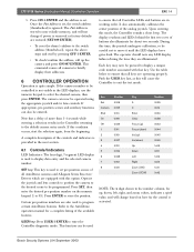
.... In some cases, it can be pressed to different speed responses. ON key: This key is used to program certain AutoDome features. Bosch Security Systems | 04 September 2003 When the first numeric key is pressed, the LED display will move the zoom lens in the camera ... to the AutoDome operation manual for a complete listing of the available features. Refer to clear incorrect data without leaving the current mode. LTC 5136 Series | Instruction Manual | Controller Operation EN | 15 CAMERA key: This key is only used to recall pre-position scenes of all AutoDome cameras ...
.... In some cases, it can be pressed to different speed responses. ON key: This key is used to program certain AutoDome features. Bosch Security Systems | 04 September 2003 When the first numeric key is pressed, the LED display will move the zoom lens in the camera ... to the AutoDome operation manual for a complete listing of the available features. Refer to clear incorrect data without leaving the current mode. LTC 5136 Series | Instruction Manual | Controller Operation EN | 15 CAMERA key: This key is only used to recall pre-position scenes of all AutoDome cameras ...
Instruction Manual
Page 16
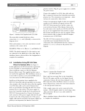
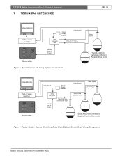
LTC 5136 Series | Instruction Manual | Technical Reference 7 TECHNICAL REFERENCE EN | 16 Video Monitor DVR or Video Switcher Data Converter Unit Power Supply Adapter Video Signal Up to 16 ... Daisy Chain Biphase Data Typical AutoDome Cameras or Allegiant Receiver/Driver units Figure 4 Typical Multiple Camera Sites Using Daisy Chain Biphase Control Code Wiring Configuration Bosch Security Systems | 04 September 2003
LTC 5136 Series | Instruction Manual | Technical Reference 7 TECHNICAL REFERENCE EN | 16 Video Monitor DVR or Video Switcher Data Converter Unit Power Supply Adapter Video Signal Up to 16 ... Daisy Chain Biphase Data Typical AutoDome Cameras or Allegiant Receiver/Driver units Figure 4 Typical Multiple Camera Sites Using Daisy Chain Biphase Control Code Wiring Configuration Bosch Security Systems | 04 September 2003
Instruction Manual
Page 17
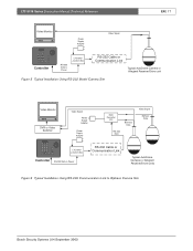
LTC 5136 Series | Instruction Manual | Technical Reference EN | 17 Video Monitor Power Supply Adapter Video Signal Controller RS-232 Data & Power LTC 8557 Junction Box RS-232 Cable or Communication Link Typical AutoDome Camera or Allegiant Receiver/Driver unit Figure 5 Typical Installation... or Video Switcher Video Signal Power Supply Adapter Power Supply Adapter Data Converter Unit Biphase Data RS-232 Data Video Signal Biphase Data LTC 8557 Junction Box Controller RS-232 Data & Power RS-232 Cable or Communication Link Typical AutoDome Cameras or Allegiant Receiver/Driver units...
LTC 5136 Series | Instruction Manual | Technical Reference EN | 17 Video Monitor Power Supply Adapter Video Signal Controller RS-232 Data & Power LTC 8557 Junction Box RS-232 Cable or Communication Link Typical AutoDome Camera or Allegiant Receiver/Driver unit Figure 5 Typical Installation... or Video Switcher Video Signal Power Supply Adapter Power Supply Adapter Data Converter Unit Biphase Data RS-232 Data Video Signal Biphase Data LTC 8557 Junction Box Controller RS-232 Data & Power RS-232 Cable or Communication Link Typical AutoDome Cameras or Allegiant Receiver/Driver units...
Instruction Manual
Page 18
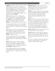
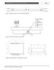
Tx 5. Rx (Not used 3. LTC 5136 Series | Instruction Manual | Technical Reference Pin 6 Pin 1 Figure 7 Supplied 6-Conductor 3 m (10 ft) Data Cable Detail EN | 18 Pin 1 Pin 6 Connector Pinouts: 1. 12V 2. Signal Ground 6. 12V Pin 6 Figure 8 Rear Panel Controller Connector Detail Pin 1 154 6.08 108 122 4.26 4.80 38 1 .5 70 2.75 mm in Figure 9 Mounting Dimensions of Supplied Interface Box 127 5.0 132 mm 5.2 in Bosch Security Systems | 04 September 2003 Not used ) 4.
Tx 5. Rx (Not used 3. LTC 5136 Series | Instruction Manual | Technical Reference Pin 6 Pin 1 Figure 7 Supplied 6-Conductor 3 m (10 ft) Data Cable Detail EN | 18 Pin 1 Pin 6 Connector Pinouts: 1. 12V 2. Signal Ground 6. 12V Pin 6 Figure 8 Rear Panel Controller Connector Detail Pin 1 154 6.08 108 122 4.26 4.80 38 1 .5 70 2.75 mm in Figure 9 Mounting Dimensions of Supplied Interface Box 127 5.0 132 mm 5.2 in Bosch Security Systems | 04 September 2003 Not used ) 4.
Instruction Manual
Page 19
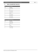
RJ-11 Designations (If Used) Pin Connection 1 Output Voltage 2 Signal Ground 3 Rx 4 Ground 5 No Connection 6 Output Voltage EN | 19 Bosch Security Systems | 04 September 2003 LTC 5136 Series | Instruction Manual | Data Converter Pinouts 8 DATA CONVERTER PINOUTS Data In - 9-Pin Connector (Male) Pin Connection 1 No Connection 2 Rx 3 No Connection 4 No Connection 5 Ground 6 No Connection 7 No Connection 8 No Connection 9 No Connection KBD -
RJ-11 Designations (If Used) Pin Connection 1 Output Voltage 2 Signal Ground 3 Rx 4 Ground 5 No Connection 6 Output Voltage EN | 19 Bosch Security Systems | 04 September 2003 LTC 5136 Series | Instruction Manual | Data Converter Pinouts 8 DATA CONVERTER PINOUTS Data In - 9-Pin Connector (Male) Pin Connection 1 No Connection 2 Rx 3 No Connection 4 No Connection 5 Ground 6 No Connection 7 No Connection 8 No Connection 9 No Connection KBD -