
User Manual
Page 7
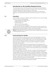
... the IntuiKey Model and device under keyboard control. If SHOT is enabled, and the key flashes red. pressing a numeric key places that the softkey display initially shows a default menu tailored to the device under the camera title). In Terminal Mode, the third-party software application determines the displayed text via the IntuiKey display screen. Bosch Security System, Inc. User Manual F.01U.127.291 | 1.93 | 2009.03 To avoid inadvertent mode changes, you...
... the IntuiKey Model and device under keyboard control. If SHOT is enabled, and the key flashes red. pressing a numeric key places that the softkey display initially shows a default menu tailored to the device under the camera title). In Terminal Mode, the third-party software application determines the displayed text via the IntuiKey display screen. Bosch Security System, Inc. User Manual F.01U.127.291 | 1.93 | 2009.03 To avoid inadvertent mode changes, you...
User Manual
Page 8
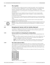
....03 User Manual Bosch Security System, Inc. PROD. If using Divar XF, Divar MR, and Divar Easy up to the Main Product Selection menu. - Use of the joystick to the control of the screen can always be used to the right of the joystick, are rocker-style buttons that are connected, the arrow softkeys at the back of the Allegiant Video Switchers, AutoDome® Series Cameras and other...
....03 User Manual Bosch Security System, Inc. PROD. If using Divar XF, Divar MR, and Divar Easy up to the Main Product Selection menu. - Use of the joystick to the control of the screen can always be used to the right of the joystick, are rocker-style buttons that are connected, the arrow softkeys at the back of the Allegiant Video Switchers, AutoDome® Series Cameras and other...
User Manual
Page 9
.... Bosch Security System, Inc. Assignments remain even if power is lost . When the IntuiKey is restored, this screen. 2. NOTICE! User Manual F.01U.127.291 | 1.93 | 2009.03 After communication with the device is first connected up to 10 characters maximum) at the bottom of the camera number. Selecting a Device for Numeric Entry (Camera Control) 1. The additional key entries add digits to put the keyboard in the display...
.... Bosch Security System, Inc. Assignments remain even if power is lost . When the IntuiKey is restored, this screen. 2. NOTICE! User Manual F.01U.127.291 | 1.93 | 2009.03 After communication with the device is first connected up to 10 characters maximum) at the bottom of the camera number. Selecting a Device for Numeric Entry (Camera Control) 1. The additional key entries add digits to put the keyboard in the display...
User Manual
Page 11
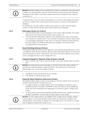
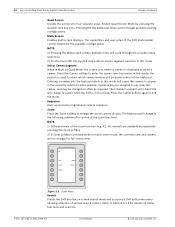
... Main Control menu to the KBD-Universal Model only. - The keyboard generates a short, audible "beep" when first entering the Allegiant log-in - Monitor Camera 123 1234 Allegiant Figure 2.1 Status Display in Four-digit Allegiant Mode Monitor Camera 123 99 1234 Allegiant Figure 2.2 Status Display in Six-digit Allegiant Mode Bosch Security System, Inc. The status display requests a PASSWORD. If user log-on the camera display mode, either four-digit or six-digit. IntuiKey Keyboard Controlling Allegiant Series Video Switchers | en 7 2 Controlling Allegiant Series Video...
... Main Control menu to the KBD-Universal Model only. - The keyboard generates a short, audible "beep" when first entering the Allegiant log-in - Monitor Camera 123 1234 Allegiant Figure 2.1 Status Display in Four-digit Allegiant Mode Monitor Camera 123 99 1234 Allegiant Figure 2.2 Status Display in Six-digit Allegiant Mode Bosch Security System, Inc. The status display requests a PASSWORD. If user log-on the camera display mode, either four-digit or six-digit. IntuiKey Keyboard Controlling Allegiant Series Video Switchers | en 7 2 Controlling Allegiant Series Video...
User Manual
Page 19
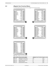
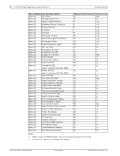
... Time Event Enable/ Disable Exit Adjust Display Position Brightness Status Selection Display Option Set Time Set Date 21 24 Exit Select Control Code FMT Select Printer Verbosity Printer Port Mode Select Crosspnt. Data DIU Interface Exit Set Camera ID Set Monitor ID Display CPU Version Reset System Vertical Sync Adjust 22 Figure 2.11 Allegiant User Function Menus Menu Softkey Function Description Menu 20 Display User #/Priority Menu 20 Change User Password Menu 20 Menu 20 Menu 20 Show Keyboard Port # Keyboard Audio Display Battery Status Bosch Security System...
... Time Event Enable/ Disable Exit Adjust Display Position Brightness Status Selection Display Option Set Time Set Date 21 24 Exit Select Control Code FMT Select Printer Verbosity Printer Port Mode Select Crosspnt. Data DIU Interface Exit Set Camera ID Set Monitor ID Display CPU Version Reset System Vertical Sync Adjust 22 Figure 2.11 Allegiant User Function Menus Menu Softkey Function Description Menu 20 Display User #/Priority Menu 20 Change User Password Menu 20 Menu 20 Menu 20 Show Keyboard Port # Keyboard Audio Display Battery Status Bosch Security System...
User Manual
Page 20
... Monitor Overlays Select Alarm Response Menu 23 Set Alarm Monitor Type Menu 23 Menu 23 Time Event Enable/Disable Select Keyboard Login Menu 23 Select Console Login Menu 23 Menu 23 Menu 23 Menu 24 Print Configuration Tables Print Sequence Tables User Function Index Select Control Code Format Menu 24 Select Printer Verbosity Menu 24 Printer Port Mode Menu 24 Menu 24 Select Crosspoint Data DIU Interface Menu 24 Menu 24 Menu 24 Camera Indicator Set Controllable Cameras R/D Address Mode Menu 24 Cache Remote Cameras Menu 24 Auto Phase Adjustment Allegiant User Function # Access...
... Monitor Overlays Select Alarm Response Menu 23 Set Alarm Monitor Type Menu 23 Menu 23 Time Event Enable/Disable Select Keyboard Login Menu 23 Select Console Login Menu 23 Menu 23 Menu 23 Menu 24 Print Configuration Tables Print Sequence Tables User Function Index Select Control Code Format Menu 24 Select Printer Verbosity Menu 24 Printer Port Mode Menu 24 Menu 24 Select Crosspoint Data DIU Interface Menu 24 Menu 24 Menu 24 Camera Indicator Set Controllable Cameras R/D Address Mode Menu 24 Cache Remote Cameras Menu 24 Auto Phase Adjustment Allegiant User Function # Access...
User Manual
Page 21
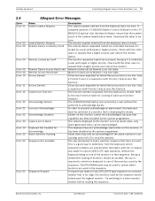
... monitor number before loading the sequence. Alarm video may be acknowledged if the alarm switcher is not running; A request was pressed by a user without the keyboard being on a monitor number that sequence. Monitor locked out by the system programmer. The function number requested from the keyboard, which sequence numbers are used to one . The camera displayed on this function. The PROGRAM mode may only be used in the sequence. Download the...
... monitor number before loading the sequence. Alarm video may be acknowledged if the alarm switcher is not running; A request was pressed by a user without the keyboard being on a monitor number that sequence. Monitor locked out by the system programmer. The function number requested from the keyboard, which sequence numbers are used to one . The camera displayed on this function. The PROGRAM mode may only be used in the sequence. Download the...
User Manual
Page 22
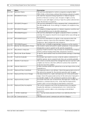
... load a sequence that the keyboard-tosystem cable is already programming a sequence on this indicates a communications error. The sequence being edited in the PROGRAM mode. Delete unused sequences, then program the new sequence. Another user is not producing an intermittent connection. Check the appropriate section of alarm monitors may be used for a valid command was made to access a remote camera connected to a satellite system, but there is only...
... load a sequence that the keyboard-tosystem cable is already programming a sequence on this indicates a communications error. The sequence being edited in the PROGRAM mode. Delete unused sequences, then program the new sequence. Another user is not producing an intermittent connection. Check the appropriate section of alarm monitors may be used for a valid command was made to access a remote camera connected to a satellite system, but there is only...
User Manual
Page 26
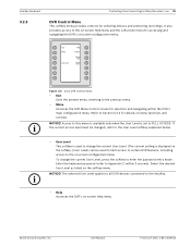
... programmed camera sequence. - The capabilities and user setup of the DVR model under control of the keyboard. Refer to the following submenu for details on -screen search mode and accesses a DVR softscreen menu allowing selection of the zoom function (e.g. In this mode will change to appear in this mode, the joystick is called a cameo. X2, X4, normal) are available by pressing the Quad Screen key once. 22 en | Controlling Divar Series Digital Video Recorders...
... programmed camera sequence. - The capabilities and user setup of the DVR model under control of the keyboard. Refer to the following submenu for details on -screen search mode and accesses a DVR softscreen menu allowing selection of the zoom function (e.g. In this mode will change to appear in this mode, the joystick is called a cameo. X2, X4, normal) are available by pressing the Quad Screen key once. 22 en | Controlling Divar Series Digital Video Recorders...
User Manual
Page 29
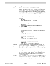
... to the User Level softkey explained below. - User Level This softkey is used to change the current User Level, press the softkey to FULL ACCESS. Select the desired User Level as listed on -screen Help menu. Help Accesses the DVR's on the softkey menu. Bosch Security System, Inc. Menu Accesses the DVR Menu Control screen for accessing and navigating the DVR's on-screen configuration menu. To change the current User Level. (The current setting is set to enter the password entry mode. User Manual F.01U.127...
... to the User Level softkey explained below. - User Level This softkey is used to change the current User Level, press the softkey to FULL ACCESS. Select the desired User Level as listed on -screen Help menu. Help Accesses the DVR's on the softkey menu. Bosch Security System, Inc. Menu Accesses the DVR Menu Control screen for accessing and navigating the DVR's on-screen configuration menu. To change the current User Level. (The current setting is set to enter the password entry mode. User Manual F.01U.127...
User Manual
Page 35
... right one level higher when in menu mode. - If the current user level does not allow the operation, a warning message is displayed on -screen control menu provides softkey access for this level of access). Bosch Security System, Inc. Exit by pressing any key. Enter the keyboard password (refer to the IntuiKey. Default: FREEZE Changes an entry to the multiplexer's quick key commands. Enable/Disable Used in Set Action Zones in approximately two (2) seconds or...
... right one level higher when in menu mode. - If the current user level does not allow the operation, a warning message is displayed on -screen control menu provides softkey access for this level of access). Bosch Security System, Inc. Exit by pressing any key. Enter the keyboard password (refer to the IntuiKey. Default: FREEZE Changes an entry to the multiplexer's quick key commands. Enable/Disable Used in Set Action Zones in approximately two (2) seconds or...
User Manual
Page 36
... Error 4 Multiplexer Not Found entered. Upon entering an Allplex number, press ENTER. This toggle button is used to enable or disable the keyboard audio beeper that entry of a multiplexer address is present. F.01U.127.291 | 1.93 | 2009.03 User Manual Bosch Security System, Inc. Enabling or disabling this softkey displays a short message on the keyboard. No multiplexers were found during search. The IntuiKey status display changes to the keyboard...
... Error 4 Multiplexer Not Found entered. Upon entering an Allplex number, press ENTER. This toggle button is used to enable or disable the keyboard audio beeper that entry of a multiplexer address is present. F.01U.127.291 | 1.93 | 2009.03 User Manual Bosch Security System, Inc. Enabling or disabling this softkey displays a short message on the keyboard. No multiplexers were found during search. The IntuiKey status display changes to the keyboard...
User Manual
Page 39
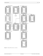
.../ Auto Pan Conventional Receiver/Driver Commands Figure A.3 Keyboard Menu Structure, continued Camera Lens 36 Commands Exit Iris Control Auto Iris ALC Adjust Auto Iris Level Adjust Auto Iris Enable Iris Polarity Focus Control Auto Focus Enable Spot Focus Digital Zoom Lock Focus Polarity Zoom Polarity Camera 37 Commands 1 Exit Backlight Comp. Camera 41 Commands Exit Fast Address Display Fast Address All Fast Address Unassigned Aux On Aux Off Bosch Security System...
.../ Auto Pan Conventional Receiver/Driver Commands Figure A.3 Keyboard Menu Structure, continued Camera Lens 36 Commands Exit Iris Control Auto Iris ALC Adjust Auto Iris Level Adjust Auto Iris Enable Iris Polarity Focus Control Auto Focus Enable Spot Focus Digital Zoom Lock Focus Polarity Zoom Polarity Camera 37 Commands 1 Exit Backlight Comp. Camera 41 Commands Exit Fast Address Display Fast Address All Fast Address Unassigned Aux On Aux Off Bosch Security System...

Instruction Manual
Page 6
... 28 VAC. F.01U.115.018 | 1.92 | 2008.12 Installation Manual Bosch Security Systems, Inc. 2 en | Safety IntuiKey Keyboard 11. Damage requiring service - the power supply cord or plug is damaged; - Replacement parts - Installation - Only use attachments/accessories specified by the manufacturer, or that have the same characteristics as : - Refer all servicing to ensure proper operating condition. 16. unit has been dropped or the unit...
... 28 VAC. F.01U.115.018 | 1.92 | 2008.12 Installation Manual Bosch Security Systems, Inc. 2 en | Safety IntuiKey Keyboard 11. Damage requiring service - the power supply cord or plug is damaged; - Replacement parts - Installation - Only use attachments/accessories specified by the manufacturer, or that have the same characteristics as : - Refer all servicing to ensure proper operating condition. 16. unit has been dropped or the unit...

Instruction Manual
Page 7
... to the unit. All-pole power switch - Camera grounding - This symbol indicates an imminently hazardous situation such as the main disconnect device for servicing and/or other activities, use caution and care when moving the cart/apparatus combination to ground the system using the ground connection of the power supply connector (see section: Connecting external power supply). Medium risk: ! Low risk...
... to the unit. All-pole power switch - Camera grounding - This symbol indicates an imminently hazardous situation such as the main disconnect device for servicing and/or other activities, use caution and care when moving the cart/apparatus combination to ground the system using the ground connection of the power supply connector (see section: Connecting external power supply). Medium risk: ! Low risk...

Instruction Manual
Page 12
... 5721 413 Email: RMADesk@STService@nl.bosch.com More information For additional information, please contact your Bosch Security Systems representative or visit our web site at www.boschsecurity.com F.01U.115.018 | 1.92 | 2008.12 Installation Manual Bosch Security Systems, Inc. 8 en | Safety 1.4 IntuiKey Keyboard Customer Support and Service If this unit needs service, contact the nearest Bosch Security Systems Service Center for authorization to return and shipping instructions.
... 5721 413 Email: RMADesk@STService@nl.bosch.com More information For additional information, please contact your Bosch Security Systems representative or visit our web site at www.boschsecurity.com F.01U.115.018 | 1.92 | 2008.12 Installation Manual Bosch Security Systems, Inc. 8 en | Safety 1.4 IntuiKey Keyboard Customer Support and Service If this unit needs service, contact the nearest Bosch Security Systems Service Center for authorization to return and shipping instructions.
Instruction Manual
Page 13
... a detailed list of IntuiKey setup. IntuiKey Keyboard with the IntuiKey Keyboards includes an external power supply, rack mount kit, and keyboard extenders. Using the optional KBD-SFTCFG software package (sold separately), customized menu screens can be used with existing Bosch products enables the IntuiKey's integration into almost any items are missing, notify your Bosch Security Systems Sales Representative or Customer Service Representative. The KBD-Digital provides control of the keyboard is completely controlled by...
... a detailed list of IntuiKey setup. IntuiKey Keyboard with the IntuiKey Keyboards includes an external power supply, rack mount kit, and keyboard extenders. Using the optional KBD-SFTCFG software package (sold separately), customized menu screens can be used with existing Bosch products enables the IntuiKey's integration into almost any items are missing, notify your Bosch Security Systems Sales Representative or Customer Service Representative. The KBD-Digital provides control of the keyboard is completely controlled by...
Instruction Manual
Page 22
....018 | 1.92 | 2008.12 Installation Manual Bosch Security Systems, Inc. The port remains in Figure 3.6. Allegiant system main CPU bay User-supplied female 9-pin D connector CONSOLE port on Allegiant system must be set to details shown in the keyboard mode unless manually cancelled by entering Ctrl-C several times using the LTC 8712 Series Console Port Expander, as a PC running the Allegiant Master Control software, can be connected to a PC for the...
....018 | 1.92 | 2008.12 Installation Manual Bosch Security Systems, Inc. The port remains in Figure 3.6. Allegiant system main CPU bay User-supplied female 9-pin D connector CONSOLE port on Allegiant system must be set to details shown in the keyboard mode unless manually cancelled by entering Ctrl-C several times using the LTC 8712 Series Console Port Expander, as a PC running the Allegiant Master Control software, can be connected to a PC for the...

Instruction Manual
Page 24
....115.018 | 1.92 | 2008.12 Installation Manual Bosch Security Systems, Inc. The following information and procedures for the Keyboard Control Mode. Connect the other end of the keyboard. The RS-232 keyboard can now be connected to the system. If desired, the Bosch Security Systems cable S1385 can be used. Connect the data cable supplied with the LTC 8712 Console Port Expander between the keyboard and the thirdparty PC is not...
....115.018 | 1.92 | 2008.12 Installation Manual Bosch Security Systems, Inc. The following information and procedures for the Keyboard Control Mode. Connect the other end of the keyboard. The RS-232 keyboard can now be connected to the system. If desired, the Bosch Security Systems cable S1385 can be used. Connect the data cable supplied with the LTC 8712 Console Port Expander between the keyboard and the thirdparty PC is not...

Instruction Manual
Page 28
....12 Installation Manual Bosch Security Systems, Inc. Ensure that all camera functions are accessible via the AutoDome's Advanced Menu. An error has been detected in firmware upgrade mode. No softkey is possible that you do not wish to the Software Update section of G3A Dome Version 2.0, all cabling is correct. - therefore, unlock the camera commands manually. - Upon powering up the keyboard, the bootloader screen appears with the message Bootloader User Requested: - Camera...
....12 Installation Manual Bosch Security Systems, Inc. Ensure that all camera functions are accessible via the AutoDome's Advanced Menu. An error has been detected in firmware upgrade mode. No softkey is possible that you do not wish to the Software Update section of G3A Dome Version 2.0, all cabling is correct. - therefore, unlock the camera commands manually. - Upon powering up the keyboard, the bootloader screen appears with the message Bootloader User Requested: - Camera...


