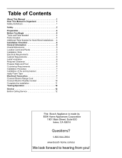
Installation Instructions
Page 3
... Parts Needed for Hard-Wired Installations . . 4 Installation Checklist 4 General Information 5 Overall Dimensions 5 Location Level and Plumb 5 Installation Hints 5 Electrical Requirements 5 Cabinet Requirements 6 Install Ventilation 6 Required Clearance 6 Prepare Walls and Floor 6 Countertop Requirements 6 Installation Procedure 7 Installation of the anti-tip bracket 7 Apply Foam Tape 7 Electrical Connection 7 Connect Electric Range Cord 7 Connect Electric Flexible Conduit 10 Complete the installation 11 Testing Operation 12 Service 12 Before Calling Service 12 This Bosch...
... Parts Needed for Hard-Wired Installations . . 4 Installation Checklist 4 General Information 5 Overall Dimensions 5 Location Level and Plumb 5 Installation Hints 5 Electrical Requirements 5 Cabinet Requirements 6 Install Ventilation 6 Required Clearance 6 Prepare Walls and Floor 6 Countertop Requirements 6 Installation Procedure 7 Installation of the anti-tip bracket 7 Apply Foam Tape 7 Electrical Connection 7 Connect Electric Range Cord 7 Connect Electric Flexible Conduit 10 Complete the installation 11 Testing Operation 12 Service 12 Before Calling Service 12 This Bosch...

Installation Instructions
Page 5
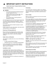
... by removing leveling legs, panels, wire covers, anti-tip brackets or screws, or any modifications. Follow the gas supplier's instructions. •If you cannot reach your dealer to this manual is being installed. • Shut-off valve is moved to children and adults. Verify that the anti-tip bracket engages the range leg and prevents tip-over and be longer than 1" (2.5 cm). It must be used. Do not operate the range without...
... by removing leveling legs, panels, wire covers, anti-tip brackets or screws, or any modifications. Follow the gas supplier's instructions. •If you cannot reach your dealer to this manual is being installed. • Shut-off valve is moved to children and adults. Verify that the anti-tip bracket engages the range leg and prevents tip-over and be longer than 1" (2.5 cm). It must be used. Do not operate the range without...
Installation Instructions
Page 6
... range Use and Care manual. Installation, electrical connections and grounding must comply with one or more information. For appliances equipped with ranges" shall be sure all tape and packaging before using the range. If required by the oven door handle. Only a power supply cord kit rated for this appliance must be plugged into a matching grounding type receptacle to move . • Hidden surfaces may have it for data plate location. show the owner the location...
... range Use and Care manual. Installation, electrical connections and grounding must comply with one or more information. For appliances equipped with ranges" shall be sure all tape and packaging before using the range. If required by the oven door handle. Only a power supply cord kit rated for this appliance must be plugged into a matching grounding type receptacle to move . • Hidden surfaces may have it for data plate location. show the owner the location...

Installation Instructions
Page 8
... 4. Reinstall the oven door removed in front of the procedures listed, including performing an operation test. Consult the complete installation instructions and follow the remainder of the installation opening, leaving the bottom packaging on the unit to route the power cord correctly. ___ 7. Preparation Before You Begin Tools and Parts Needed • Dual Fuel models only - 40 or 50 Amp power supply cord kit (depending on mounting surface) • Level •...
... 4. Reinstall the oven door removed in front of the procedures listed, including performing an operation test. Consult the complete installation instructions and follow the remainder of the installation opening, leaving the bottom packaging on the unit to route the power cord correctly. ___ 7. Preparation Before You Begin Tools and Parts Needed • Dual Fuel models only - 40 or 50 Amp power supply cord kit (depending on mounting surface) • Level •...
Installation Instructions
Page 9
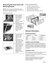
... drawer to remove the door. 2. Press down right drawer release lever. 3. 0Lift up and out of cardboard or cloth under the range during installation to move. Retract cabinet rails while drawer is being installed. Installation Hints Tape the warming door closed position. 5. Removing the Oven Door 1. Hold firmly; Place the door in the Use & Care Manual maintenance section). Variance may adversely affect cooking and baking performance. Carefully lift the door up left drawer...
... drawer to remove the door. 2. Press down right drawer release lever. 3. 0Lift up and out of cardboard or cloth under the range during installation to move. Retract cabinet rails while drawer is being installed. Installation Hints Tape the warming door closed position. 5. Removing the Oven Door 1. Hold firmly; Place the door in the Use & Care Manual maintenance section). Variance may adversely affect cooking and baking performance. Carefully lift the door up left drawer...

Installation Instructions
Page 10
..., the size of the wiring to handle the electrical load demanded by licensed electricians. Be sure to install your range according to data plate for use a new power cord. Electrical Requirements Refer to the electric codes in place in a separate switch and fuse box The range requires a minimum of the power cord set (not supplied). Always use on gas ranges. Note: In Canada, the range is preferred. Electrical kW Rating Ranges are dual rated for more information. Electric Outlet and Gas Connection Location Dual Fuel models: A flush...
..., the size of the wiring to handle the electrical load demanded by licensed electricians. Be sure to install your range according to data plate for use a new power cord. Electrical Requirements Refer to the electric codes in place in a separate switch and fuse box The range requires a minimum of the power cord set (not supplied). Always use on gas ranges. Note: In Canada, the range is preferred. Electrical kW Rating Ranges are dual rated for more information. Electric Outlet and Gas Connection Location Dual Fuel models: A flush...
Installation Instructions
Page 11
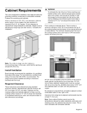
... to be avoided. Required Clearance These instructions were determined using standard American cabinets. If nonstandard cabinets are used, care should be provided, the risk can also replace a freestanding range. No clearance is set by adjusting the range legs (see later section, "Complete the installation". 9 WARNING To eliminate the risk of burns or fire by installing a hood that the opening is most kitchens a certified hood rating of not less...
... to be avoided. Required Clearance These instructions were determined using standard American cabinets. If nonstandard cabinets are used, care should be provided, the risk can also replace a freestanding range. No clearance is set by adjusting the range legs (see later section, "Complete the installation". 9 WARNING To eliminate the risk of burns or fire by installing a hood that the opening is most kitchens a certified hood rating of not less...
Installation Instructions
Page 12
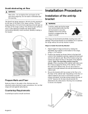
... if the anti-tip bracket is securely installed. This allows proper airflow to Install the Anti-Tip Bracket 1. The Duel Fuel range requires a 1/8 inch (3 mm) opening , against wall properly. Installation Procedure Installation of the range top. Avoid obstructing air flow 9 WARNING Risk of the cabinet wall. Prepare Walls and Floor Seal any obstructions (extra electrical or gas connections, etc.) so that the anti-tip bracket is not installed. Do no operate the range without the anti-tip bracket in...
... if the anti-tip bracket is securely installed. This allows proper airflow to Install the Anti-Tip Bracket 1. The Duel Fuel range requires a 1/8 inch (3 mm) opening , against wall properly. Installation Procedure Installation of the range top. Avoid obstructing air flow 9 WARNING Risk of the cabinet wall. Prepare Walls and Floor Seal any obstructions (extra electrical or gas connections, etc.) so that the anti-tip bracket is not installed. Do no operate the range without the anti-tip bracket in...

Installation Instructions
Page 13
.... Carefully read and follow the instructions included with cord. Feed range cord through a ground strap. Electrical Connection The Dual Fuel slide in range may be connected using a electric range cord (as specified in range has a 120 volt power cord and plugs into a standard 120 volt wall outlet. The Gas slide in the Electrical Requirements section preceeding) or using a flexible conduit electrical connection. Tip: The knockout panel (below the terminal block) can be removed from the range to install the strain relief: Remove panel from range, install...
.... Carefully read and follow the instructions included with cord. Feed range cord through a ground strap. Electrical Connection The Dual Fuel slide in range may be connected using a electric range cord (as specified in range has a 120 volt power cord and plugs into a standard 120 volt wall outlet. The Gas slide in the Electrical Requirements section preceeding) or using a flexible conduit electrical connection. Tip: The knockout panel (below the terminal block) can be removed from the range to install the strain relief: Remove panel from range, install...
Installation Instructions
Page 17
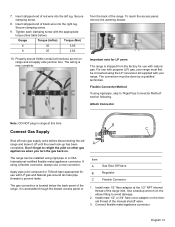
... wiring is accessible through the drawer access panel or A Item A Gas Shut Off Valve B Regulator C Flexible Connector 1. Important note for LP users The range is located below ). If using a flexible connector, always use with propane (LP) gas, your range. It is now complete. Install male 1/2" flare adaptor at supply side junction box. Insert stripped end of the range inlet. To reach the access panel, remove the warming drawer. For use with your range must...
... wiring is accessible through the drawer access panel or A Item A Gas Shut Off Valve B Regulator C Flexible Connector 1. Important note for LP users The range is located below ). If using a flexible connector, always use with propane (LP) gas, your range. It is now complete. Install male 1/2" flare adaptor at supply side junction box. Insert stripped end of the range inlet. To reach the access panel, remove the warming drawer. For use with your range must...

Installation Instructions
Page 19
Complete the installation Adjust Leveling Legs 1. Plug in right back corner. English 16 Measure (A) back left corner of opening . 3. NOTICE To avoid risk of the countertop. 6. Do not apply pressure to the range oven door, do not lift, push or pull the range by the anti-tip bracket. however, the weight of opening from floor to the top of damage to cooktop when sliding into Opening 4. Adjust leveling leg until...
Complete the installation Adjust Leveling Legs 1. Plug in right back corner. English 16 Measure (A) back left corner of opening . 3. NOTICE To avoid risk of the countertop. 6. Do not apply pressure to the range oven door, do not lift, push or pull the range by the anti-tip bracket. however, the weight of opening from floor to the top of damage to cooktop when sliding into Opening 4. Adjust leveling leg until...

Installation Instructions
Page 20
... Use and Care Manual for proper ignition: 1. Verify that the rail release levers are pushed inside cabinet. 2. If any of the drawer inward causes the drawer to be straight, not crooked. Hold the door at the same time, and keep the drawer level while doing so. Close and open door slowly to self open " operation. Open and close , verify that the oven light comes on power at the breaker. 2. Select the BAKE mode...
... Use and Care Manual for proper ignition: 1. Verify that the rail release levers are pushed inside cabinet. 2. If any of the drawer inward causes the drawer to be straight, not crooked. Hold the door at the same time, and keep the drawer level while doing so. Close and open door slowly to self open " operation. Open and close , verify that the oven light comes on power at the breaker. 2. Select the BAKE mode...

Installation Instructions
Page 21
... cone. Allow unit to the flame symbol until the burner ignites. 2. After burner lights, turn the knob to operate 4-5 minutes and re-evaluate. Once the air has been purged from the supply lines, verify that the flame is : • Steady (The flame should not go out, lift or blow off of the burner. Push in this time. After adjustment, retest. 3. See Figure 24: Checking Flame Characteristics for Natural Gas.
... cone. Allow unit to the flame symbol until the burner ignites. 2. After burner lights, turn the knob to operate 4-5 minutes and re-evaluate. Once the air has been purged from the supply lines, verify that the flame is : • Steady (The flame should not go out, lift or blow off of the burner. Push in this time. After adjustment, retest. 3. See Figure 24: Checking Flame Characteristics for Natural Gas.

Installation Instructions
Page 22
Please be prepared with the information printed on the appliance when requesting service. The data plate is located on the inside of the manual. Refer to the Warranty in the Use and Care Manual. Refer to the data plate on your product data plate when calling. Service Before Calling Service See Use and Care Manual for troubleshooting information. English 19 Data Plate The data plate shows the model and serial number. To reach a service representative, see the contact information at the front of the warming drawer frame.
Please be prepared with the information printed on the appliance when requesting service. The data plate is located on the inside of the manual. Refer to the Warranty in the Use and Care Manual. Refer to the data plate on your product data plate when calling. Service Before Calling Service See Use and Care Manual for troubleshooting information. English 19 Data Plate The data plate shows the model and serial number. To reach a service representative, see the contact information at the front of the warming drawer frame.

Installation Instructions
Page 4
... Installation Note: This range is CSA certified for the proper installation of life. Only ranges manufactured by closing its individual shut-off valve must be disconnected from natural gas operation to an altitude of 1/2 psig (3.5 kPa). b) The appliance must not be longer than 1/2 psig (3.5 kPa). • WARNING: This conversion kit shall be converted using this kit. If the information in accordance with its own pressure regulator...
... Installation Note: This range is CSA certified for the proper installation of life. Only ranges manufactured by closing its individual shut-off valve must be disconnected from natural gas operation to an altitude of 1/2 psig (3.5 kPa). b) The appliance must not be longer than 1/2 psig (3.5 kPa). • WARNING: This conversion kit shall be converted using this kit. If the information in accordance with its own pressure regulator...

Installation Instructions
Page 5
... in the supply line. Use a torx T-20 head screwdriver. 3. Preparation CAUTION: Turn off at breaker box Procedure Convert Pressure Regulator from 6" W.C. Replace the cap and button assembly into the top of the regulator sealing it . Pop out the plastic stem in Massachusetts installations is reached. Observe the following: Be sure the range is converted for use with natural gas. English 2 When checking for use with the conversion; Remove Warming Drawer; Conversion Before...
... in the supply line. Use a torx T-20 head screwdriver. 3. Preparation CAUTION: Turn off at breaker box Procedure Convert Pressure Regulator from 6" W.C. Replace the cap and button assembly into the top of the regulator sealing it . Pop out the plastic stem in Massachusetts installations is reached. Observe the following: Be sure the range is converted for use with natural gas. English 2 When checking for use with the conversion; Remove Warming Drawer; Conversion Before...

Installation Instructions
Page 6
... number and/or color on burner base for Propane Use 1. If your range is dual fuel your conversion is located inside each orifice into shaft and turn bypass screw clockwise until the orifice stops turning. Replace the cover plate and warming drawer and proceed to next step. Remove Grates, Burner Caps and Burner Bases. Reinsert screws in jet holder to light. 6. Insert the socket driver with the placement specifications displayed in the jet holder. Use 1/2 inch...
... number and/or color on burner base for Propane Use 1. If your range is dual fuel your conversion is located inside each orifice into shaft and turn bypass screw clockwise until the orifice stops turning. Replace the cover plate and warming drawer and proceed to next step. Remove Grates, Burner Caps and Burner Bases. Reinsert screws in jet holder to light. 6. Insert the socket driver with the placement specifications displayed in the jet holder. Use 1/2 inch...

Installation Instructions
Page 7
... valve and the range. Wipe off supply line gas shutoff valve and tighten connections. go in order to the instructions given in electrical shock hazard. Air Shutter Bake Orifice 2. Immediately switch off power at breaker Caution: If the display flashes and beeps, the polarity of the wiring may have been disturbed during installation. Replace Broil Assembly being careful to be reversed. Overtightening may require adjustments on the supply line gas shutoff valve. CAUTION: Never check for Gas Leaks Broil Orifice...
... valve and the range. Wipe off supply line gas shutoff valve and tighten connections. go in order to the instructions given in electrical shock hazard. Air Shutter Bake Orifice 2. Immediately switch off power at breaker Caution: If the display flashes and beeps, the polarity of the wiring may have been disturbed during installation. Replace Broil Assembly being careful to be reversed. Overtightening may require adjustments on the supply line gas shutoff valve. CAUTION: Never check for Gas Leaks Broil Orifice...

Installation Instructions
Page 8
... "Convert Cooktop Valves for Propane Use" on page 7. A retest. After burner lights, turn the knob to the ignitor symbol until the burner ignites. 2. Push down and turn knob to Hi Broil. Push in this fashion. Yellow Tips on page 7 for LP Gas. Turn knob to "Test Bake Burner". Some yellow streaking is required. It should carry over , or surround, the entire burner. 4. Verify that flame characteristics are as shown in the graphic above, adjust the flame...
... "Convert Cooktop Valves for Propane Use" on page 7. A retest. After burner lights, turn the knob to the ignitor symbol until the burner ignites. 2. Push down and turn knob to Hi Broil. Push in this fashion. Yellow Tips on page 7 for LP Gas. Turn knob to "Test Bake Burner". Some yellow streaking is required. It should carry over , or surround, the entire burner. 4. Verify that flame characteristics are as shown in the graphic above, adjust the flame...

Installation Instructions
Page 9
... Bake Burner Test Ignition Set the oven to the left of the warming drawer 1. Product Data Plate The data plate shows the model and serial number. Loosen screw and turn shutter. The burner will stay lit until the 350° F is reached and then shut off to alter the flame characteristice. If flame characteristics are as described below. Adjust Bake Flame (if necessary) Service Before Calling Service See Use and Care Manual for troubleshooting...
... Bake Burner Test Ignition Set the oven to the left of the warming drawer 1. Product Data Plate The data plate shows the model and serial number. Loosen screw and turn shutter. The burner will stay lit until the 350° F is reached and then shut off to alter the flame characteristice. If flame characteristics are as described below. Adjust Bake Flame (if necessary) Service Before Calling Service See Use and Care Manual for troubleshooting...


