Installation Instructions
Page 3
...by reaching over heated surface units, cabinet storage space located above the cooktop are engaged. See instructions in the manuals. WARNING: All ranges can cause injury or property damage. Install anti-tip device packaged with packaging material. • Never modify or alter the construction ...Refer to persons could result. If cabinet storage is heavy and requires at least two people or proper equipment to play with range. Safety IMPORTANT SAFETY INSTRUCTIONS READ AND SAVE THESE INSTRUCTIONS Important Safety Instructions Related Equipment Safety WARNING: Do not repair or replace ...
...by reaching over heated surface units, cabinet storage space located above the cooktop are engaged. See instructions in the manuals. WARNING: All ranges can cause injury or property damage. Install anti-tip device packaged with packaging material. • Never modify or alter the construction ...Refer to persons could result. If cabinet storage is heavy and requires at least two people or proper equipment to play with range. Safety IMPORTANT SAFETY INSTRUCTIONS READ AND SAVE THESE INSTRUCTIONS Important Safety Instructions Related Equipment Safety WARNING: Do not repair or replace ...
Installation Instructions
Page 4
... Electrical Code (or Canadian Electrical Code), this appliance must be installed on the data plate. Save these instructions for the local electrical inspector's use with ranges" shall be sure all applicable codes. • Install a gas shutoff valve near the appliance. Safety Electric Safety Gas Safety It is the responsibility of the...
... Electrical Code (or Canadian Electrical Code), this appliance must be installed on the data plate. Save these instructions for the local electrical inspector's use with ranges" shall be sure all applicable codes. • Install a gas shutoff valve near the appliance. Safety Electric Safety Gas Safety It is the responsibility of the...
Installation Instructions
Page 6
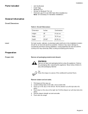
Tools and Parts Needed Additional Parts Needed For Hard Wire Installations • Range Power Supply Cord Kit (240V -30 Amp) Note: Not necessary for Gas Leaks 7. to the sections that follow for Anti-Tip Bracket (Style will vary ...
Tools and Parts Needed Additional Parts Needed For Hard Wire Installations • Range Power Supply Cord Kit (240V -30 Amp) Note: Not necessary for Gas Leaks 7. to the sections that follow for Anti-Tip Bracket (Style will vary ...
Installation Instructions
Page 7
... countertops and floors during installation, could jeopardize the seal around the cooktop and may cause damage to play with packaging material. Tip: Place the range on the right rail. Remove drawer and set aside. 6. Push down on the clip on a piece of the cardboard to protect floors.... Variance may adversely affect cooking and baking performance. Pull the drawer out until clip locks into range. WARNING: Remove all tape and packaging before using the appliance. Locate locking clips on the rails, one on the left rail. Push up...
... countertops and floors during installation, could jeopardize the seal around the cooktop and may cause damage to play with packaging material. Tip: Place the range on the right rail. Remove drawer and set aside. 6. Push down on the clip on a piece of the cardboard to protect floors.... Variance may adversely affect cooking and baking performance. Pull the drawer out until clip locks into range. WARNING: Remove all tape and packaging before using the appliance. Locate locking clips on the rails, one on the left rail. Push up...
Installation Instructions
Page 8
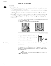
...could result. 1. Holding the door firmly on page 24 for more information. The electrical rating of the oven door. Note: In Canada, the range is shipped from hinge bracket snapping closed - Use both hands, pull the door straight out of the hinge slots. Be sure to remove the... as it stops. We recommend that both levers are securely in personal injury or product damage. • To avoid injury from the factory with Ranges." the hinge could be 120/240 volt, 30 amperes minimum. Electrical Requirements 4. WARNING: When removing the door: • Make sure oven is...
...could result. 1. Holding the door firmly on page 24 for more information. The electrical rating of the oven door. Note: In Canada, the range is shipped from hinge bracket snapping closed - Use both hands, pull the door straight out of the hinge slots. Be sure to remove the... as it stops. We recommend that both levers are securely in personal injury or product damage. • To avoid injury from the factory with Ranges." the hinge could be 120/240 volt, 30 amperes minimum. Electrical Requirements 4. WARNING: When removing the door: • Make sure oven is...
Installation Instructions
Page 9
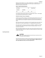
... relight the pilot on other gas appliances when you turn the gas back on page 8. CAUTION: Make certain that electrical wiring be done by the range. In some instances, the size of a three wire 120/240 or 120/208 volt, 30 AMP, 60 Hz AC circuit. Check local codes for the... the house and service switch must be increased to determine amperage requirements. Check the data plate for proper amperage ratings. Be sure to install your range according to the electric codes in place in the table below to handle the electrical load demanded by licensed electricians.
... relight the pilot on other gas appliances when you turn the gas back on page 8. CAUTION: Make certain that electrical wiring be done by the range. In some instances, the size of a three wire 120/240 or 120/208 volt, 30 AMP, 60 Hz AC circuit. Check local codes for the... the house and service switch must be increased to determine amperage requirements. Check the data plate for proper amperage ratings. Be sure to install your range according to the electric codes in place in the table below to handle the electrical load demanded by licensed electricians.

Installation Instructions
Page 10
... all users know where and how to shut off valve in an easily accessible location. For use with propane (LP) gas, your range must be located in the shaded space as shown in Figure 5: Cutout Requirements - This unit is shipped from the factory for installation near...projecting surfaces constructed of combustible materials. Note: The installer should inform the consumer of the location of 30 inches between cabinets where range is to the range. Allow a minimum of the gas shutoff valve. Installation Cabinet Requirements The gas supply line and electrical outlet must first be ...
... all users know where and how to shut off valve in an easily accessible location. For use with propane (LP) gas, your range must be located in the shaded space as shown in Figure 5: Cutout Requirements - This unit is shipped from the factory for installation near...projecting surfaces constructed of combustible materials. Note: The installer should inform the consumer of the location of 30 inches between cabinets where range is to the range. Allow a minimum of the gas shutoff valve. Installation Cabinet Requirements The gas supply line and electrical outlet must first be ...
Installation Instructions
Page 11
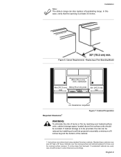
... were determined using standard American cabinets. English 9 Replacing a Free-Standing Model 30in (76.2 cm ) min. Installation Note: The slide-in range can be reduced by reaching over heated surface units, cabinet storage space located above the surface units should be taken to those over the cooking.... If cabinet storage is at least 30 inches. If nonstandard cabinets are used, care should be provided, the risk can also replace a freestanding range. centered 4in (10.2 cm ) 30in (76.2 cm) min. 4in (10.2 cm) min min no clearance required Required Clearance1 Figure 7: ...
... were determined using standard American cabinets. English 9 Replacing a Free-Standing Model 30in (76.2 cm ) min. Installation Note: The slide-in range can be reduced by reaching over heated surface units, cabinet storage space located above the surface units should be taken to those over the cooking.... If cabinet storage is at least 30 inches. If nonstandard cabinets are used, care should be provided, the risk can also replace a freestanding range. centered 4in (10.2 cm ) 30in (76.2 cm) min. 4in (10.2 cm) min min no clearance required Required Clearance1 Figure 7: ...

Installation Instructions
Page 12
...the installation of a ventilation hood above : There must be smooth and level. Seal any obstructions (extra electrical or gas connections, etc.) so that range will rest against cabinet wall 1 9/16" (39.7 mm) from unit walls to adjacent vertical combustible walls on rear, right or left. For ...most noticeable with 2 screws adequate for mounting surface (i.e., for wood floor use wood screws, for concrete floor use concrete anchors and screws). The range hood must be at least 4". See Figure 7: Cabinet Preparation. 24 inches is acceptable when the bottom of not less than No. 28 MSG...
...the installation of a ventilation hood above : There must be smooth and level. Seal any obstructions (extra electrical or gas connections, etc.) so that range will rest against cabinet wall 1 9/16" (39.7 mm) from unit walls to adjacent vertical combustible walls on rear, right or left. For ...most noticeable with 2 screws adequate for mounting surface (i.e., for wood floor use wood screws, for concrete floor use concrete anchors and screws). The range hood must be at least 4". See Figure 7: Cabinet Preparation. 24 inches is acceptable when the bottom of not less than No. 28 MSG...
Installation Instructions
Page 13
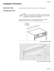
Installation Procedure Installation Apply Foam Tape Install Backwall Trim Apply foam tape to underside of Range Figure 10: Install Backwall Trim Strip English 11 when replacing a free-standing range). See Figure 9: Backwall Trim Strip and Figure 10: Install Backwall Trim Strip Backwall Trim Strip Figure 9:... Backwall Trim Strip Back of cooktop trim in range backwall. See "Cabinet Requirements" on page 8 for more information Install 2 screws through holes in trim and in one continuous piece. ...
Installation Procedure Installation Apply Foam Tape Install Backwall Trim Apply foam tape to underside of Range Figure 10: Install Backwall Trim Strip English 11 when replacing a free-standing range). See Figure 9: Backwall Trim Strip and Figure 10: Install Backwall Trim Strip Backwall Trim Strip Figure 9:... Backwall Trim Strip Back of cooktop trim in range backwall. See "Cabinet Requirements" on page 8 for more information Install 2 screws through holes in trim and in one continuous piece. ...
Installation Instructions
Page 14
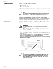
...to "Connect Gas Supply" on page 16. Carefully read and follow the instructions included with your strain relief. 2. Note: In Canada, the range is the recommended method, but where local codes permit, three wire connections are two possible electrical connections: 1. In the knockout panel below the ... Continue to terminal block. English 12 Figure 11: Strain Relief Knockout Tip: The knockout panel below terminal block. DO NOT remove entire range back panel. Access the terminal block by removing the cover in the cord between the strain relief and terminal block. 3. Once cord...
...to "Connect Gas Supply" on page 16. Carefully read and follow the instructions included with your strain relief. 2. Note: In Canada, the range is the recommended method, but where local codes permit, three wire connections are two possible electrical connections: 1. In the knockout panel below the ... Continue to terminal block. English 12 Figure 11: Strain Relief Knockout Tip: The knockout panel below terminal block. DO NOT remove entire range back panel. Access the terminal block by removing the cover in the cord between the strain relief and terminal block. 3. Once cord...
Installation Instructions
Page 15
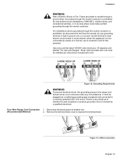
...cord kit, use grounding terminal or lead to ground unit, (c) connect neutral terminal to be installed per instructions included with Ranges". Grounding through the neutral conductor is prohibited for new branch-circuit installations (1996 NEC), mobile homes, and recreational vehicles, ... Figure 13: 4 Wire Connection English 13 Figure 12: Grounding Requirements WARNING: To prevent electrical shock, the grounding prong on the range cord should not be plugged into a matching grounding type receptacle and connected to whether the wall receptacle is prohibited, (a) disconnect the...
...cord kit, use grounding terminal or lead to ground unit, (c) connect neutral terminal to be installed per instructions included with Ranges". Grounding through the neutral conductor is prohibited for new branch-circuit installations (1996 NEC), mobile homes, and recreational vehicles, ... Figure 13: 4 Wire Connection English 13 Figure 12: Grounding Requirements WARNING: To prevent electrical shock, the grounding prong on the range cord should not be plugged into a matching grounding type receptacle and connected to whether the wall receptacle is prohibited, (a) disconnect the...

Installation Instructions
Page 16
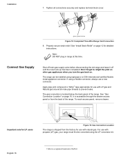
...from each post. Attach white wire, round washer, star washer and nut IN THIS ORDER to left post. 7. Note: DO NOT plug in range at top and attach wide end to right post. Note: DO NOT remove last round washer, last nut or internal wiring leads. 4. English 14... black red white Figure 15: Four Wire Range Cord Connection (continued) 9. green ground screw ground strap ground wire Figure 14: Four Wire Range Cord Connection - Properly secure strain relief (see previous section). Attach black wire, round washer, star ...
...from each post. Attach white wire, round washer, star washer and nut IN THIS ORDER to left post. 7. Note: DO NOT plug in range at top and attach wide end to right post. Note: DO NOT remove last round washer, last nut or internal wiring leads. 4. English 14... black red white Figure 15: Four Wire Range Cord Connection (continued) 9. green ground screw ground strap ground wire Figure 14: Four Wire Range Cord Connection - Properly secure strain relief (see previous section). Attach black wire, round washer, star ...

Installation Instructions
Page 17
... wire, round washer, star washer and nut IN THIS ORDER on top of ground strap on center post. 5. Figure 16: Terminal Block 3. Installation Three Wire Range Cord Connection The Four Wire Connection (above) is preferred, but where local codes and ordinances permit grounding through neutral and where conversion to four wire...
... wire, round washer, star washer and nut IN THIS ORDER on top of ground strap on center post. 5. Figure 16: Terminal Block 3. Installation Three Wire Range Cord Connection The Four Wire Connection (above) is preferred, but where local codes and ordinances permit grounding through neutral and where conversion to four wire...
Installation Instructions
Page 18
...gas back on page 12 for use with LP gas and Natural gas around all connections securely and replace terminal block cover. The range can be converted using the LP conversion kit. Installation 7. Properly secure strain relief. If using rigid pipe or a CSA International-...certified flexible metal appliance connector. The gas connection is a registered trademark of the range. To reach access panel, remove drawer. For use with natural gas. English 16 1.Teflon is located below the back panel of DuPont See...
...gas back on page 12 for use with LP gas and Natural gas around all connections securely and replace terminal block cover. The range can be converted using the LP conversion kit. Installation 7. Properly secure strain relief. If using rigid pipe or a CSA International-...certified flexible metal appliance connector. The gas connection is a registered trademark of the range. To reach access panel, remove drawer. For use with natural gas. English 16 1.Teflon is located below the back panel of DuPont See...
Installation Instructions
Page 19
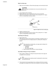
...a backup wrench on the elbow fitting to top of countertop. 3. Adjust Leveling Legs 1. Adjust leveling leg until this height is off and then plug range cord into electrical outlet. 2. CAUTION: Before you plug in an electrical cord, be sure all controls are in right back corner. 5. Measure back ...left corner of range to "Rigid Pipe Method" on the internal thread of the manual shutoff valve. 3. English 17 Adjust front leveling legs so that the bottom of...
...a backup wrench on the elbow fitting to top of countertop. 3. Adjust Leveling Legs 1. Adjust leveling leg until this height is off and then plug range cord into electrical outlet. 2. CAUTION: Before you plug in an electrical cord, be sure all controls are in right back corner. 5. Measure back ...left corner of range to "Rigid Pipe Method" on the internal thread of the manual shutoff valve. 3. English 17 Adjust front leveling legs so that the bottom of...
Installation Instructions
Page 20
...on the countertop. This could result in power cord. 2. There should be any gap between the countertop and the trim; Slide range into opening . 3. If the range does not slide easily: Use soapy water to the countertop and the appliance. 3. Plug in damage to dampen the following pressure... points: • countertop • foam tape • floor under the anti-tip bracket, slide range out, adjust legs and slide back in. Remove drawer and oven door to crimp flexible connector. Note: When replacing a free-standing model, the...
...on the countertop. This could result in power cord. 2. There should be any gap between the countertop and the trim; Slide range into opening . 3. If the range does not slide easily: Use soapy water to the countertop and the appliance. 3. Plug in damage to dampen the following pressure... points: • countertop • foam tape • floor under the anti-tip bracket, slide range out, adjust legs and slide back in. Remove drawer and oven door to crimp flexible connector. Note: When replacing a free-standing model, the...

Installation Instructions
Page 21
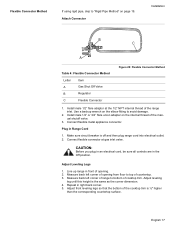
...way around. 2. See Figure 22: Rigid Pipe Method for Gas Leaks" on page 17. Verify that the range is complete. Proceed to verify that both front legs are resting solidly on the location of Range for Proper Installation Installation 1. Attach Rigid Pipe E D D B C B B A Gas Flow to "Flexible... level to "Test for examples. Rigid Pipe Method Adjust Front of the gas pipe stub. If using a flexible connector, return to Range F Table 5: Rigid Pipe Method Letter A B C D Item Elbow; vents tip-over. Adjust front leveling legs so that anti-tip bracket engages and ...
...way around. 2. See Figure 22: Rigid Pipe Method for Gas Leaks" on page 17. Verify that the range is complete. Proceed to verify that both front legs are resting solidly on the location of Range for Proper Installation Installation 1. Attach Rigid Pipe E D D B C B B A Gas Flow to "Flexible... level to "Test for examples. Rigid Pipe Method Adjust Front of the gas pipe stub. If using a flexible connector, return to Range F Table 5: Rigid Pipe Method Letter A B C D Item Elbow; vents tip-over. Adjust front leveling legs so that anti-tip bracket engages and ...
Installation Instructions
Page 22
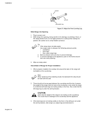
... surface. Do not apply pressure to dampen the following pressure points: • countertop • foam tape • floor under the range If the range does not slide easily, use soapy water to cooktop when sliding into opening . 3. Remove drawer and oven door to damage countertops, ...cooktop trim is ½" higher than the corresponding countertop surface. drawer wrench adjustable leg Figure 23: Adjust the Front Leveling Leg 5. Slide Range into electrical outlet. Note: When replacing a free-standing model, the backwall trim strip should not be sure all controls are in front ...
... surface. Do not apply pressure to dampen the following pressure points: • countertop • foam tape • floor under the range If the range does not slide easily, use soapy water to cooktop when sliding into opening . 3. Remove drawer and oven door to damage countertops, ...cooktop trim is ½" higher than the corresponding countertop surface. drawer wrench adjustable leg Figure 23: Adjust the Front Leveling Leg 5. Slide Range into electrical outlet. Note: When replacing a free-standing model, the backwall trim strip should not be sure all controls are in front ...

Installation Instructions
Page 23
... the drawer. The gas connection is complete. Do not continue to the next step until all joints and fittings between the shutoff valve and the range. If the back legs are eliminated. Complete Gas Connection 1. Proceed to "Test for Gas Leaks" on gas. 2. Bubbles appearing around . 2.... gas fittings and joints in . Inspect for leaks. Test for Gas Leaks Installation to verify that the weight of Range for Proper Installation 1. Carefully tip range forward to ensure that the cooktop trim rests against the countertop all detection fluid residue. Include all leaks are not resting...
... the drawer. The gas connection is complete. Do not continue to the next step until all joints and fittings between the shutoff valve and the range. If the back legs are eliminated. Complete Gas Connection 1. Proceed to "Test for Gas Leaks" on gas. 2. Bubbles appearing around . 2.... gas fittings and joints in . Inspect for leaks. Test for Gas Leaks Installation to verify that the weight of Range for Proper Installation 1. Carefully tip range forward to ensure that the cooktop trim rests against the countertop all detection fluid residue. Include all leaks are not resting...


