Installation Instructions
Page 2
Huntington Beach, CA 92649 We look forward to hearing from you! Table of Contents Safety 1 Important Safety Instructions 1 Installation 4 Before You Begin 4 Overview 4 Tools and Parts Needed 4 Parts Included 5 General Information 5 Preparation 5 Installation Procedure 11 Apply Foam Tape 11 Install Backwall Trim 11 Connect Electric 12 Connect Gas Supply 16 Test for Gas Leaks 21 Test the Installation 22 Service 24 Before Calling Service 24 Product Data Plate 24 Questions? 1-800-944-2904 www.boschappliances.com 5551 McFadden Ave.
Huntington Beach, CA 92649 We look forward to hearing from you! Table of Contents Safety 1 Important Safety Instructions 1 Installation 4 Before You Begin 4 Overview 4 Tools and Parts Needed 4 Parts Included 5 General Information 5 Preparation 5 Installation Procedure 11 Apply Foam Tape 11 Install Backwall Trim 11 Connect Electric 12 Connect Gas Supply 16 Test for Gas Leaks 21 Test the Installation 22 Service 24 Before Calling Service 24 Product Data Plate 24 Questions? 1-800-944-2904 www.boschappliances.com 5551 McFadden Ave.
Installation Instructions
Page 3
... result. WARNING: All ranges can cause injury or property damage. For example, do not remove leveling legs, panels, wire covers or anti-tip brackets/screws. • To eliminate the risk of Electric Fans • ANSI Z21.1, The American National Standard for the Safety of burns or fire by reaching over heated surface units, cabinet storage space located above the cooktop are engaged. Use caution when reaching...
... result. WARNING: All ranges can cause injury or property damage. For example, do not remove leveling legs, panels, wire covers or anti-tip brackets/screws. • To eliminate the risk of Electric Fans • ANSI Z21.1, The American National Standard for the Safety of burns or fire by reaching over heated surface units, cabinet storage space located above the cooktop are engaged. Use caution when reaching...
Installation Instructions
Page 4
... of the circuit breaker or fuse. Mark it checked by a qualified electrician. • If required by a qualified tech- English 2 If there is properly installed and grounded by the National Electrical Code (or Canadian Electrical Code), this appliance must be 1" water column above the manifold pressure printed on a separate branch circuit. • Only a power-supply cord kit rated for easy reference. • Important - Lock service panel to or...
... of the circuit breaker or fuse. Mark it checked by a qualified electrician. • If required by a qualified tech- English 2 If there is properly installed and grounded by the National Electrical Code (or Canadian Electrical Code), this appliance must be 1" water column above the manifold pressure printed on a separate branch circuit. • Only a power-supply cord kit rated for easy reference. • Important - Lock service panel to or...
Installation Instructions
Page 5
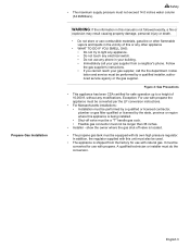
... from a neighbor's phone. Propane Gas Installation Safety • The maximum supply pressure must do the conversion. Exception: For use with propane the appliance must be converted per the LP conversion instructions. • For Massachusetts installations: • Installation must be longer than 36 inches. • Installer - English 3 WARNING: If the information in this manual is located. • The propane gas tank must be converted for use with propane. Installation and service must be performed by...
... from a neighbor's phone. Propane Gas Installation Safety • The maximum supply pressure must do the conversion. Exception: For use with propane the appliance must be converted per the LP conversion instructions. • For Massachusetts installations: • Installation must be longer than 36 inches. • Installer - English 3 WARNING: If the information in this manual is located. • The propane gas tank must be converted for use with propane. Installation and service must be performed by...
Installation Instructions
Page 6
... Gas Leaks 7. Apply Foam Tape 3. Connect Electric 5. Tools and Parts Needed Additional Parts Needed For Hard Wire Installations • Range Power Supply Cord Kit (240V -30 Amp) Note: Not necessary for Anti-Tip Bracket (Style will vary depending on mounting surface) • Level • Drill and Drill Bit • Soapy Water • Pipe Wrench • Teflon Tape • Channel Lock Pliers • Gas Leak Test Solution • Gas Supply Line • Gas Shut Off Valve...
... Gas Leaks 7. Apply Foam Tape 3. Connect Electric 5. Tools and Parts Needed Additional Parts Needed For Hard Wire Installations • Range Power Supply Cord Kit (240V -30 Amp) Note: Not necessary for Anti-Tip Bracket (Style will vary depending on mounting surface) • Level • Drill and Drill Bit • Soapy Water • Pipe Wrench • Teflon Tape • Channel Lock Pliers • Gas Leak Test Solution • Gas Supply Line • Gas Shut Off Valve...
Installation Instructions
Page 7
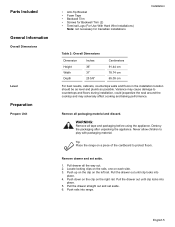
Parts Included General Information Overall Dimensions Level Preparation Prepare Unit • Anti-Tip Bracket • Foam Tape • Backwall Trim • Screws for Backwall Trim (2) • Terminal Lugs (For Use With Hard Wire Installations) Note: not necessary for Canadian installations Installation Table 2: Overall Dimensions Dimension Height Width Depth Inches 36" 31" 25 5/8" Centimeters 91.44 cm 78.74 cm 65.09 cm For best results, cabinets, countertops walls...
Parts Included General Information Overall Dimensions Level Preparation Prepare Unit • Anti-Tip Bracket • Foam Tape • Backwall Trim • Screws for Backwall Trim (2) • Terminal Lugs (For Use With Hard Wire Installations) Note: not necessary for Canadian installations Installation Table 2: Overall Dimensions Dimension Height Width Depth Inches 36" 31" 25 5/8" Centimeters 91.44 cm 78.74 cm 65.09 cm For best results, cabinets, countertops walls...
Installation Instructions
Page 8
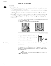
... remove the oven door. See "Product Data Plate" on each side) toward you. The electrical rating of the oven door. The power cord set must be marked "For Use with Ranges." Always use a new power cord. Installation Remove oven door and set (not supplied). The door front is heavy. 6. Do not grasp the handle as it stops. the hinge could be about halfway open or closed , be sure that the range be installed with the range cord already installed...
... remove the oven door. See "Product Data Plate" on each side) toward you. The electrical rating of the oven door. The power cord set must be marked "For Use with Ranges." Always use a new power cord. Installation Remove oven door and set (not supplied). The door front is heavy. 6. Do not grasp the handle as it stops. the hinge could be about halfway open or closed , be sure that the range be installed with the range cord already installed...
Installation Instructions
Page 9
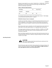
... regulations and codes require that gas shutoff valve and all burner controls are dual rated for use on either in the main entrance panel or in a separate switch and fuse box. Don't forget to the electric codes in place in your home is preferred. The range requires a minimum of the wiring to the house and service switch must be located in the shaded space shown in "Gas Supply Line and Electrical Outlet Placement" on . A four wire connection...
... regulations and codes require that gas shutoff valve and all burner controls are dual rated for use on either in the main entrance panel or in a separate switch and fuse box. Don't forget to the electric codes in place in your home is preferred. The range requires a minimum of the wiring to the house and service switch must be located in the shaded space shown in "Gas Supply Line and Electrical Outlet Placement" on . A four wire connection...

Installation Instructions
Page 10
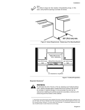
For use with propane (LP) gas, your range must be located in the shaded space as shown in an easily accessible location. Allow a minimum of 30 inches between cabinets where range is to be converted using the LP conversion kit. Typical Installation. Typical Installation Important note for LP users The range is designed for use with natural gas. Prepare the countertop and cabinets as shown in Figure 4: Gas Supply Line and Electrical Outlet Placement...
For use with propane (LP) gas, your range must be located in the shaded space as shown in an easily accessible location. Allow a minimum of 30 inches between cabinets where range is to be converted using the LP conversion kit. Typical Installation. Typical Installation Important note for LP users The range is designed for use with natural gas. Prepare the countertop and cabinets as shown in Figure 4: Gas Supply Line and Electrical Outlet Placement...
Installation Instructions
Page 11
... also replace a freestanding range. Instructions were determined using standard American cabinets. Installation Note: The slide-in range can be reduced by reaching over the cooking surface measure 13 inches deep from backwall. In this case, verify that projects horizontally a minimum of 5 inches beyond the bottom of burns or fire by installing a hood that the opening is to those over heated surface units, cabinet storage space located above the surface...
... also replace a freestanding range. Instructions were determined using standard American cabinets. Installation Note: The slide-in range can be reduced by reaching over the cooking surface measure 13 inches deep from backwall. In this case, verify that projects horizontally a minimum of 5 inches beyond the bottom of burns or fire by installing a hood that the opening is to those over heated surface units, cabinet storage space located above the surface...

Installation Instructions
Page 12
... cabinet is required from range top to adjacent vertical walls must be smooth and level. Install Anti-Tip Bracket 1. Note: Some cabinet finishes cannot survive the temperatures allowed by (a) not less than 300 CFM is most kitchens a certified hood rating of not less than 1/4" of flame retardant material which must be a minimum clearance of 30 inches between the top of the cooking surface and the...
... cabinet is required from range top to adjacent vertical walls must be smooth and level. Install Anti-Tip Bracket 1. Note: Some cabinet finishes cannot survive the temperatures allowed by (a) not less than 300 CFM is most kitchens a certified hood rating of not less than 1/4" of flame retardant material which must be a minimum clearance of 30 inches between the top of the cooking surface and the...
Installation Instructions
Page 14
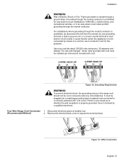
... local codes permit, three wire connections are two possible electrical connections: 1. Allow for detailed instructions). Strain reliefs vary. Access the terminal block by removing the cover in the cord between the strain relief and terminal block. 3. See Figure 11: Strain Relief Knockout. Once cord length/ slack has been adjusted, attach strain relief per instructions included with your strain relief. 1. In the knockout panel...
... local codes permit, three wire connections are two possible electrical connections: 1. Allow for detailed instructions). Strain reliefs vary. Access the terminal block by removing the cover in the cord between the strain relief and terminal block. 3. See Figure 11: Strain Relief Knockout. Once cord length/ slack has been adjusted, attach strain relief per instructions included with your strain relief. 1. In the knockout panel...
Installation Instructions
Page 15
... Requirements WARNING: To prevent electrical shock, the grounding prong on the range cord should not be cut or removed under any doubt as to a correctly polarized 240- Four Wire Range Cord Connection 1. Disconnect electrical power at breaker box. (Recommended Method) 2. Strain relief provided with cord must be plugged into a matching grounding type receptacle and connected to whether the wall receptacle is to be installed per instructions included with Ranges". Installation...
... Requirements WARNING: To prevent electrical shock, the grounding prong on the range cord should not be cut or removed under any doubt as to a correctly polarized 240- Four Wire Range Cord Connection 1. Disconnect electrical power at breaker box. (Recommended Method) 2. Strain relief provided with cord must be plugged into a matching grounding type receptacle and connected to whether the wall receptacle is to be installed per instructions included with Ranges". Installation...
Installation Instructions
Page 18
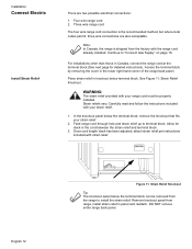
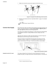
... relief. The range can be converted using the LP conversion kit. To reach access panel, remove drawer. For use with natural gas. Connect Gas Supply Shut off main gas supply valve before disconnecting the old range and leave it off until the new hook-up has been completed. It is a registered trademark of the range. English 16 1.Teflon is accessible through the drawer access panel or from the factory for detailed instructions. Tighten...
... relief. The range can be converted using the LP conversion kit. To reach access panel, remove drawer. For use with natural gas. Connect Gas Supply Shut off main gas supply valve before disconnecting the old range and leave it off until the new hook-up has been completed. It is a registered trademark of the range. English 16 1.Teflon is accessible through the drawer access panel or from the factory for detailed instructions. Tighten...
Installation Instructions
Page 19
... of the manual shutoff valve. 3. English 17 Plug in the Off position. Measure back left corner of the cooktop trim is off and then plug range cord into electrical outlet. 2. Adjust front leveling legs so that the bottom of opening . 2. Make sure circuit breaker is ½" higher than the corresponding countertop surface. CAUTION: Before you plug in an electrical cord, be sure all controls are in Range Cord 1. Line up range in...
... of the manual shutoff valve. 3. English 17 Plug in the Off position. Measure back left corner of the cooktop trim is off and then plug range cord into electrical outlet. 2. Adjust front leveling legs so that the bottom of opening . 2. Make sure circuit breaker is ½" higher than the corresponding countertop surface. CAUTION: Before you plug in an electrical cord, be sure all controls are in Range Cord 1. Line up range in...
Installation Instructions
Page 20
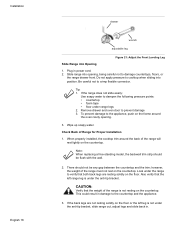
... the range will rest lightly on the countertop. Note: When replacing a free-standing model, the backwall trim strip should not be flush with the wall. 2. Look under the anti-tip bracket. If the back legs are resting solidly on the floor. Installation English 18 drawer wrench adjustable leg Figure 21: Adjust the Front Leveling Leg Slide Range into opening . 3. When properly installed, the cooktop trim around the oven cavity opening , being careful not...
... the range will rest lightly on the countertop. Note: When replacing a free-standing model, the backwall trim strip should not be flush with the wall. 2. Look under the anti-tip bracket. If the back legs are resting solidly on the floor. Installation English 18 drawer wrench adjustable leg Figure 21: Adjust the Front Leveling Leg Slide Range into opening . 3. When properly installed, the cooktop trim around the oven cavity opening , being careful not...

Installation Instructions
Page 21
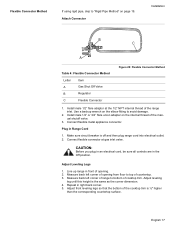
... Pipe Method for Proper Installation Installation 1. English 19 The gas connection is level and plumb. 4. Connect to regulator here Pipe Nipple Union Elbow E Gas Shut Off Valve F 1/2" to verify that both front legs are resting solidly on the location of the gas pipe stub. Adjust front leveling legs so that anti-tip bracket engages and pre- If using a flexible connector, return to ensure that the cooktop trim rests snugly against...
... Pipe Method for Proper Installation Installation 1. English 19 The gas connection is level and plumb. 4. Connect to regulator here Pipe Nipple Union Elbow E Gas Shut Off Valve F 1/2" to verify that both front legs are resting solidly on the location of the gas pipe stub. Adjust front leveling legs so that anti-tip bracket engages and pre- If using a flexible connector, return to ensure that the cooktop trim rests snugly against...
Installation Instructions
Page 22
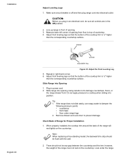
.... 2. Slide Range into position. Look under range legs 2. Line up range in power cord. 2. Do not apply pressure to cooktop when sliding into Opening 1. If the range does not slide easily, use soapy water to prevent damage Check Back of Range for Proper Installation 1. Measure back left corner of the cooktop trim is ½" higher than the corresponding countertop surface. Adjust front leveling legs so that the bottom of opening . 3. Remove drawer and oven door to...
.... 2. Slide Range into position. Look under range legs 2. Line up range in power cord. 2. Do not apply pressure to cooktop when sliding into Opening 1. If the range does not slide easily, use soapy water to prevent damage Check Back of Range for Proper Installation 1. Measure back left corner of the cooktop trim is ½" higher than the corresponding countertop surface. Adjust front leveling legs so that the bottom of opening . 3. Remove drawer and oven door to...

Installation Instructions
Page 23
.... Complete Gas Connection 1. Connect pipe to range at supply line shutoff valve and reapply leak detection fluid. 6. Proceed to "Test for leaks. Note: Be careful not to apply pressure to warming drawer element during installation. 3. Turn on the countertop. Turn gas back on at union. Adjust front leveling legs so that the cooktop trim rests against the countertop all joints and fittings between the shutoff valve and the range. vents tip-over. Include gas fittings...
.... Complete Gas Connection 1. Connect pipe to range at supply line shutoff valve and reapply leak detection fluid. 6. Proceed to "Test for leaks. Note: Be careful not to apply pressure to warming drawer element during installation. 3. Turn on the countertop. Turn gas back on at union. Adjust front leveling legs so that the cooktop trim rests against the countertop all joints and fittings between the shutoff valve and the range. vents tip-over. Include gas fittings...
Installation Instructions
Page 24
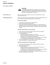
... off power at breaker Test self-clean lock Test Rangetop Burners: CAUTION: If the display flashes and beeps, the polarity of the burners do not light. English 22 After burner lights, turn the knob to the flame symbol until the burner ignites. 2. Test flame characteristics on the high setting: 1. Push in this fashion. Verify that the burner lights within four (4) seconds. Turn knob quickly to the high setting. 3. Turn knob to the low setting. 3. Cancel self-clean mode. It...
... off power at breaker Test self-clean lock Test Rangetop Burners: CAUTION: If the display flashes and beeps, the polarity of the burners do not light. English 22 After burner lights, turn the knob to the flame symbol until the burner ignites. 2. Test flame characteristics on the high setting: 1. Push in this fashion. Verify that the burner lights within four (4) seconds. Turn knob quickly to the high setting. 3. Turn knob to the low setting. 3. Cancel self-clean mode. It...


