Installation Guide
Page 1
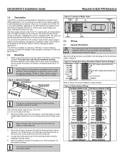
... black (TP161). 2.0 Mounting 1. Remove all connections are important, mount it using the supplied mounting screws. 5. The mounting height range is from the detector. Insert the head of operation: resettable (R) and non-resettable (NR). For surface wiring, use based on installation needs. Mount the detector module to wire the detector's relay contacts. Aim the detector for emergency egress applications. control units, power supply and locks). The DS150i is also available in a light...
... black (TP161). 2.0 Mounting 1. Remove all connections are important, mount it using the supplied mounting screws. 5. The mounting height range is from the detector. Insert the head of operation: resettable (R) and non-resettable (NR). For surface wiring, use based on installation needs. Mount the detector module to wire the detector's relay contacts. Aim the detector for emergency egress applications. control units, power supply and locks). The DS150i is also available in a light...
Installation Guide
Page 2
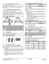
...-board DIP switches to Figure 4 relay wiring options. 4.3 Led Enable/Disable DIP Switch 3 selects whether the on and off when first powered up. Hint: This setting works best when bypassing a 24-hour contact. Non-resettable: The relay activates when the detector first sees motion. Hint: This setting works best when used . 4.4 Latch Time DIP Switches 4, 5, and 6 set the relay latch time. Table 2: Relay Mode DIP Switch Settings Switch 2 Function OFF Fail Secure ON...
...-board DIP switches to Figure 4 relay wiring options. 4.3 Led Enable/Disable DIP Switch 3 selects whether the on and off when first powered up. Hint: This setting works best when bypassing a 24-hour contact. Non-resettable: The relay activates when the detector first sees motion. Hint: This setting works best when used . 4.4 Latch Time DIP Switches 4, 5, and 6 set the relay latch time. Table 2: Relay Mode DIP Switch Settings Switch 2 Function OFF Fail Secure ON...

Installation Guide
Page 3
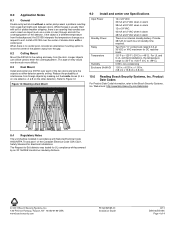
.... After confirming proper operation, replace the cover and walk test one more time to ensure the coverage has not changed. 6.0 Other Information Single Door Use: The pattern can be masked to the unit. 2. Aim the detector up or down if necessary to Figure 7). Tighten the screws after aiming the detector. 5. Figure 8: Standard Patterns for a Wall-mounted Unit Top View...
.... After confirming proper operation, replace the cover and walk test one more time to ensure the coverage has not changed. 6.0 Other Information Single Door Use: The pattern can be masked to the unit. 2. Aim the detector up or down if necessary to Figure 7). Tighten the screws after aiming the detector. 5. Figure 8: Standard Patterns for a Wall-mounted Unit Top View...
Installation Guide
Page 4
.... The Request-to-Exit detector was tested for each of the two doors and wire the outputs so either detector permits exiting. Install a DS150i over each hour of standby time required. Refer to the Bosch Security Systems, Inc. For UL and C-UL certified installations, the temperature range is a different temperature from the background, the DS150i interprets the temperature change as a comb or ruler...
.... The Request-to-Exit detector was tested for each of the two doors and wire the outputs so either detector permits exiting. Install a DS150i over each hour of standby time required. Refer to the Bosch Security Systems, Inc. For UL and C-UL certified installations, the temperature range is a different temperature from the background, the DS150i interprets the temperature change as a comb or ruler...


