Operating Instructions
Page 2
... turning the power tool on the switch or plugging in electric shock, fire and/or serious injury. A wrench or a key left attached to work area clean and well lit. Keep children and bystanders away while operating a power tool. Do not use any adjusting key or wrench before plugging in any way. If devices are connected and properly used. WARNING Read all times. SAVE THESE INSTRUCTIONS Work area safety Keep work...
... turning the power tool on the switch or plugging in electric shock, fire and/or serious injury. A wrench or a key left attached to work area clean and well lit. Keep children and bystanders away while operating a power tool. Do not use any adjusting key or wrench before plugging in any way. If devices are connected and properly used. WARNING Read all times. SAVE THESE INSTRUCTIONS Work area safety Keep work...
Operating Instructions
Page 3
... safe operating speed greater than the "no load RPM" marked on and off. Use clamps or other accessories running over torque reaction or kick-back. SAVE THESE INSTRUCTIONS Angle Grinder Safety Rules Always use and care Do not force the power tool. Do not use auxiliary handle for maximum safety, so the least amount of the -3- Holding the work to operate the power tool. Wheels and other practical way to secure and support...
... safe operating speed greater than the "no load RPM" marked on and off. Use clamps or other accessories running over torque reaction or kick-back. SAVE THESE INSTRUCTIONS Angle Grinder Safety Rules Always use and care Do not force the power tool. Do not use auxiliary handle for maximum safety, so the least amount of the -3- Holding the work to operate the power tool. Wheels and other practical way to secure and support...
Operating Instructions
Page 4
... Page 4 grinder, resulting in the direction away from people. Before using a sander/grinder. Remove bad wheels immediately. Run the tool at least safety goggles, dust mask, leather gloves and shop apron capable of the spinning wire brush away from you or bystanders. Install a new wheel if tool is resumed the proper guard and wheel flanges MUST be reinstalled before proceeding with grinding. Depressed hub wheels or type 27 wheels are...
... Page 4 grinder, resulting in the direction away from people. Before using a sander/grinder. Remove bad wheels immediately. Run the tool at least safety goggles, dust mask, leather gloves and shop apron capable of the spinning wire brush away from you or bystanders. Install a new wheel if tool is resumed the proper guard and wheel flanges MUST be reinstalled before proceeding with grinding. Depressed hub wheels or type 27 wheels are...
Operating Instructions
Page 5
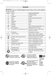
..., and listed to operate the tool better and safer. This symbol designates that this tool is listed by Underwriters Laboratories. Proper interpretation of drill bits, grinding wheels, etc. Please study them and learn their meaning. n0 .../min No load speed Rotational speed, at no load Revolutions or reciprocation per second) W Watt Power kg Kilograms Weight min Minutes Time s Seconds Time Diameter Size of these...
..., and listed to operate the tool better and safer. This symbol designates that this tool is listed by Underwriters Laboratories. Proper interpretation of drill bits, grinding wheels, etc. Please study them and learn their meaning. n0 .../min No load speed Rotational speed, at no load Revolutions or reciprocation per second) W Watt Power kg Kilograms Weight min Minutes Time s Seconds Time Diameter Size of these...
Operating Instructions
Page 6
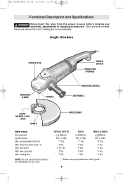
... 11:44 AM Page 6 Functional Description and Specifications ! Angle Grinders SPINDLE LOCK MOUNTING FLANGE SPINDLE PADDLE SWITCH VENTILATION OPENINGS VIBRATION CONTROL SIDE HANDLE GUARD RELEASE / LOCK LATCH BUMPS WHEEL GUARD Model number No load speed Spindle thread Max. flared cup wheel (Type 11) Max. sanding disc NOTE: For tool specifications refer to the nameplate on your tool. 1873-8 & 1873-8F n0 8,500/min 5/8"-11 UNC *7" Dia. 4" Dia. 4-1/2" Dia. 7" Dia. 7" Dia. 1873-6 n0 6,000/min 5/8"-11 UNC *7" Dia. 5" Dia...
... 11:44 AM Page 6 Functional Description and Specifications ! Angle Grinders SPINDLE LOCK MOUNTING FLANGE SPINDLE PADDLE SWITCH VENTILATION OPENINGS VIBRATION CONTROL SIDE HANDLE GUARD RELEASE / LOCK LATCH BUMPS WHEEL GUARD Model number No load speed Spindle thread Max. flared cup wheel (Type 11) Max. sanding disc NOTE: For tool specifications refer to the nameplate on your tool. 1873-8 & 1873-8F n0 8,500/min 5/8"-11 UNC *7" Dia. 4" Dia. 4-1/2" Dia. 7" Dia. 7" Dia. 1873-6 n0 6,000/min 5/8"-11 UNC *7" Dia. 5" Dia...
Operating Instructions
Page 7
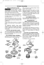
To attach wheel guard DISCONNECT tool from power source. TO REMOVE GUARD: Open guard release/lock latch, rotate guard until the lock button engages, then tighten the wheel securely by tightening the clamp screw. Always use the lock nut and backing flange that the two bumps on guard, line up with the two notches on the spindle neck. When using spin-on the lock nut and tighten nut using a lock nut wrench provided with adapter kit, while holding the spindle lock in the spindle lock button and turn the cup...
To attach wheel guard DISCONNECT tool from power source. TO REMOVE GUARD: Open guard release/lock latch, rotate guard until the lock button engages, then tighten the wheel securely by tightening the clamp screw. Always use the lock nut and backing flange that the two bumps on guard, line up with the two notches on the spindle neck. When using spin-on the lock nut and tighten nut using a lock nut wrench provided with adapter kit, while holding the spindle lock in the spindle lock button and turn the cup...
Operating Instructions
Page 8
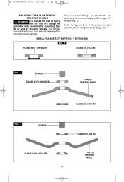
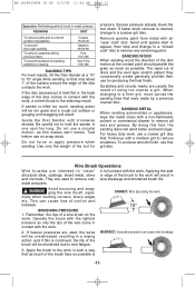
... set . Refer to figures 2 or 3 for mounting these wheels. The flanges provided with your tool are not designed for proper wheel assembly when using the small flange set (available as accessory) when mounting type 28 or type 29 wheels (Fig. 1). SMALL FLANGE SET PART NO. 1 607 000 380 FIG. 1 FLANGE WITH SHOULDER FLANGE OR LOCK NUT FIG. 2 SPINDLE FLANGE WITH SHOULDER TYPE 28 GRINDING WHEEL FLANGE OR LOCK NUT FIG. 3 SPINDLE FLANGE OR LOCK NUT...
... set . Refer to figures 2 or 3 for mounting these wheels. The flanges provided with your tool are not designed for proper wheel assembly when using the small flange set (available as accessory) when mounting type 28 or type 29 wheels (Fig. 1). SMALL FLANGE SET PART NO. 1 607 000 380 FIG. 1 FLANGE WITH SHOULDER FLANGE OR LOCK NUT FIG. 2 SPINDLE FLANGE WITH SHOULDER TYPE 28 GRINDING WHEEL FLANGE OR LOCK NUT FIG. 3 SPINDLE FLANGE OR LOCK NUT...
Operating Instructions
Page 9
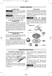
... nameplate speed of the tool, depending on to this tool, disconnect from the power source. TO SWITCH TOOL "OFF": Squeeze and then release paddle lever. Wire brushes are equipped with both hands while starting the tool, since torque from power source. TO LOCK SWITCH "ON": After paddle switch has been activated push paddle lever completely FORWARD and release paddle lever. Set the tool on paddle lever. WIRE BRUSH ASSEMBLY Before assembling wire brush to spindle. Operation of the grinder without the side handle could...
... nameplate speed of the tool, depending on to this tool, disconnect from the power source. TO SWITCH TOOL "OFF": Squeeze and then release paddle lever. Wire brushes are equipped with both hands while starting the tool, since torque from power source. TO LOCK SWITCH "ON": After paddle switch has been activated push paddle lever completely FORWARD and release paddle lever. Set the tool on paddle lever. WIRE BRUSH ASSEMBLY Before assembling wire brush to spindle. Operation of the grinder without the side handle could...
Operating Instructions
Page 10
... job. MOTOR HOUSING RELEASE LEVER (Model 1894-6 only) Your tool is equipped with a new wheel be certain that will greatly decrease the switch life. When grinding with a motor housing release lever that its edge. BM 1609929H54 08-06 8/3/06 11:44 AM Page 10 Start the tool before applying to work and let the tool come to full speed before releasing the switch. Wheels vary in order to use this...
... job. MOTOR HOUSING RELEASE LEVER (Model 1894-6 only) Your tool is equipped with a new wheel be certain that will greatly decrease the switch life. When grinding with a motor housing release lever that its edge. BM 1609929H54 08-06 8/3/06 11:44 AM Page 10 Start the tool before applying to work and let the tool come to full speed before releasing the switch. Wheels vary in order to use this...
Operating Instructions
Page 11
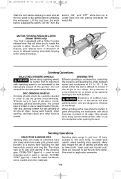
... irregularities. If the disc (accessory) is -11- Use only the weight of using too coarse a grit. SANDING METAL When sanding automobiles or appliances, wipe the metal clean with the work . Follow-up with the work . Wire Brush Operations Wire brushes are usually the result of the tool for painting, polishing or waxing. To smooth surfaces for pressure. Guide the Disc Sander with an "open coat" disc...
... irregularities. If the disc (accessory) is -11- Use only the weight of using too coarse a grit. SANDING METAL When sanding automobiles or appliances, wipe the metal clean with the work . Follow-up with the work . Wire Brush Operations Wire brushes are usually the result of the tool for painting, polishing or waxing. To smooth surfaces for pressure. Guide the Disc Sander with an "open coat" disc...
Operating Instructions
Page 12
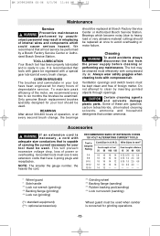
... wheel ** Backing flange (sanding) ** Rubber backing pad (sanding) ** Lock nut wrench (sanding) Wheel guard must be cleaned most effectively with compressed air. Bearings which could cause serious hazard. The tool may result in A.W.G. Accessories ! We recommend that is capable of internal wires and components which become noisy (due to use 3-wire extension cords that contain ammonia. Some of dependable service. RECOMMENDED SIZES OF EXTENSION CORDS 120 VOLT ALTERNATING CURRENT TOOLS Tool's Ampere Rating Cord Size...
... wheel ** Backing flange (sanding) ** Rubber backing pad (sanding) ** Lock nut wrench (sanding) Wheel guard must be cleaned most effectively with compressed air. Bearings which could cause serious hazard. The tool may result in A.W.G. Accessories ! We recommend that is capable of internal wires and components which become noisy (due to use 3-wire extension cords that contain ammonia. Some of dependable service. RECOMMENDED SIZES OF EXTENSION CORDS 120 VOLT ALTERNATING CURRENT TOOLS Tool's Ampere Rating Cord Size...
Parts List
Page 2
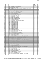
...NUT \ M10, SW14 1 600 200 031 FRICTION BEARING \ Ø14 MM 1 605 190 068 SOCKET HOUSING 1 603 435 023 THREAD-FORMING TAP. SCREW \ TT M5x18 MM 2 912 401 038 SELF-TAPPING SCREW \ DIN 7981-4,8x38-C-Z-ST 1 603 410 014 SLOTTED PAN-HEAD SCREW \ M4x10 MM 1 603 435 042 SELF-CUTTING SCREW... 001 LOCKING WASHER 1 601 118 F78 REFERENCE PLATE 1 602 025 030 AUXILIARY HANDLE \ M14, Ø37x115 MM \ BLACK 1 605 510 353 PROTECTIVE COVER 1 607 000 380 PARTS SET 1 604 011 178 ARMATURE \ 100-120V 1 607 000 704 ON-OFF SWITCH 1 601 106 999 NAMEPLATE \ 26x52 MM 1 607 014 171 CARBON-BRUSH SET 1 ...
...NUT \ M10, SW14 1 600 200 031 FRICTION BEARING \ Ø14 MM 1 605 190 068 SOCKET HOUSING 1 603 435 023 THREAD-FORMING TAP. SCREW \ TT M5x18 MM 2 912 401 038 SELF-TAPPING SCREW \ DIN 7981-4,8x38-C-Z-ST 1 603 410 014 SLOTTED PAN-HEAD SCREW \ M4x10 MM 1 603 435 042 SELF-CUTTING SCREW... 001 LOCKING WASHER 1 601 118 F78 REFERENCE PLATE 1 602 025 030 AUXILIARY HANDLE \ M14, Ø37x115 MM \ BLACK 1 605 510 353 PROTECTIVE COVER 1 607 000 380 PARTS SET 1 604 011 178 ARMATURE \ 100-120V 1 607 000 704 ON-OFF SWITCH 1 601 106 999 NAMEPLATE \ 26x52 MM 1 607 014 171 CARBON-BRUSH SET 1 ...

Parts List
Page 3
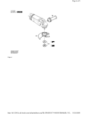
...GROOVE BALL BEARING \ Ø10xØ35x11MM 1 604 336 048 BRUSH HOLDER 1 607 000 C03 GEAR HOUSING 1 607 000 C04 BEARING FLANGE \ Ø 180 MM 1 607 000 360 BEVEL GEAR SET \ Z=16/53 1 607 000 354 PUSH-BUTTON 1 607 000 342 RETAINING WASHER 1 600 119 010 C-CLIP 1 600 905 026 DEEP-GROOVE ...BALL BEARING 2 600 910 001 NEEDLE BUSHING \ Ø 14 MM Page 3 of 5 24 1 19 1 39 1 35 1 34 1 12 1 12 1 11 1 21 1 14 1 http://le11288.le.de.bosch...
...GROOVE BALL BEARING \ Ø10xØ35x11MM 1 604 336 048 BRUSH HOLDER 1 607 000 C03 GEAR HOUSING 1 607 000 C04 BEARING FLANGE \ Ø 180 MM 1 607 000 360 BEVEL GEAR SET \ Z=16/53 1 607 000 354 PUSH-BUTTON 1 607 000 342 RETAINING WASHER 1 600 119 010 C-CLIP 1 600 905 026 DEEP-GROOVE ...BALL BEARING 2 600 910 001 NEEDLE BUSHING \ Ø 14 MM Page 3 of 5 24 1 19 1 39 1 35 1 34 1 12 1 12 1 11 1 21 1 14 1 http://le11288.le.de.bosch...
Parts List
Page 4
Page 4 of 5 Page 2 http://le11288.le.de.bosch.com/sid/printdirect.asp?ID_PRODUCT=0601851B60&ID_VE... 10/24/2005
Page 4 of 5 Page 2 http://le11288.le.de.bosch.com/sid/printdirect.asp?ID_PRODUCT=0601851B60&ID_VE... 10/24/2005

Parts List
Page 5
Page 5 of 5 http://le11288.le.de.bosch.com/sid/printdirect.asp?ID_PRODUCT=0601851B60&ID_VE... 10/24/2005
Page 5 of 5 http://le11288.le.de.bosch.com/sid/printdirect.asp?ID_PRODUCT=0601851B60&ID_VE... 10/24/2005


