Operating Instructions
Page 2
... unavoidable, use the power tool if the switch does not turn it was designed. Power tool use reduces the risk of electric shock if your hair, clothing and gloves away from heat, oil, sharp edges or moving parts. Any power tool that have the switch on . SAVE ALL WARNINGS AND INSTRUCTIONS FOR FUTURE REFERENCE The term "power tool" in all of a cord suitable for your mains-operated (corded) power tool or battery-operated (cordless) power tool. Power tools create sparks...
... unavoidable, use the power tool if the switch does not turn it was designed. Power tool use reduces the risk of electric shock if your hair, clothing and gloves away from heat, oil, sharp edges or moving parts. Any power tool that have the switch on . SAVE ALL WARNINGS AND INSTRUCTIONS FOR FUTURE REFERENCE The term "power tool" in all of a cord suitable for your mains-operated (corded) power tool or battery-operated (cordless) power tool. Power tools create sparks...

Operating Instructions
Page 3
... parts and any adjustments, changing accessories, or storing power tools. Keep handles dry, clean and free from those dust masks that may damage plastic parts. Develop a periodic maintenance schedule for operations different from oil and grease. Use clamps or other condition that are caused by a qualified repair person using only identical replacement parts. may affect the power tool's operation. Check for misalignment or binding of moving parts, breakage of starting the power tool accidentally. Use the power tool, accessories and tool bits...
... parts and any adjustments, changing accessories, or storing power tools. Keep handles dry, clean and free from those dust masks that may damage plastic parts. Develop a periodic maintenance schedule for operations different from oil and grease. Use clamps or other condition that are caused by a qualified repair person using only identical replacement parts. may affect the power tool's operation. Check for misalignment or binding of moving parts, breakage of starting the power tool accidentally. Use the power tool, accessories and tool bits...
Operating Instructions
Page 4
...". Accessories may result. Table with the blade while in , check that the trigger lock is unavoidable, disconnect all adjusting screws and the blade guide are not designed for this worksite. Never leave the trigger locked "ON". Accidental start-ups could slip out of the saw blade. Replace the blade if excessive play between uses with a moving saw must never be clamped to a workbench before next cut or removing cut . The proximity of cut...
...". Accessories may result. Table with the blade while in , check that the trigger lock is unavoidable, disconnect all adjusting screws and the blade guide are not designed for this worksite. Never leave the trigger locked "ON". Accidental start-ups could slip out of the saw blade. Replace the blade if excessive play between uses with a moving saw must never be clamped to a workbench before next cut or removing cut . The proximity of cut...
Operating Instructions
Page 5
... symbols may be used on your tool. Selector settings I, II, III, Speed, torque or position settings. Earthing terminal Grounding terminal Warning symbol Alerts user to warning messages Li-ion RBRC seal Designates Li-ion battery recycling program This symbol designates that this tool is increasing from 0 setting Arrow Action in the direction of arrow Alternating current Type or a characteristic of current Direct current Type or a characteristic...
... symbols may be used on your tool. Selector settings I, II, III, Speed, torque or position settings. Earthing terminal Grounding terminal Warning symbol Alerts user to warning messages Li-ion RBRC seal Designates Li-ion battery recycling program This symbol designates that this tool is increasing from 0 setting Arrow Action in the direction of arrow Alternating current Type or a characteristic of current Direct current Type or a characteristic...
Operating Instructions
Page 6
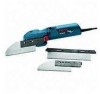
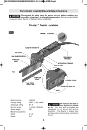
... Handsaw FIG. 1 VARIABLE SPEED DIAL SLIDE ON/OFF SWITCH LED LIGHTS SAW BLADE DRIVE PIN SAW BLADE GUIDE TAB FLUSH-CUT BLADE SAW TEETH PROTECTOR 16P4r0oVfSessional VENTILATION OPENINGS VENTILATION OPENINGS16P4r0oVfSessional CLIC BUTTON LOCKING SPRING SAW BLADE DRIVE PIN HOOK Model number Voltage rating Amperage rating No load speed Stroke length Maximum capacities: Wood Plastic 1640VS 120 V 50 - 60Hz 3.5 A n0 1,000-2,800/min 5/8" 2-1/2" 3/4" -6- ! WARNING Disconnect the plug from the power source before making any assembly, adjustments or changing accessories. Fine drywall or plaster...
... Handsaw FIG. 1 VARIABLE SPEED DIAL SLIDE ON/OFF SWITCH LED LIGHTS SAW BLADE DRIVE PIN SAW BLADE GUIDE TAB FLUSH-CUT BLADE SAW TEETH PROTECTOR 16P4r0oVfSessional VENTILATION OPENINGS VENTILATION OPENINGS16P4r0oVfSessional CLIC BUTTON LOCKING SPRING SAW BLADE DRIVE PIN HOOK Model number Voltage rating Amperage rating No load speed Stroke length Maximum capacities: Wood Plastic 1640VS 120 V 50 - 60Hz 3.5 A n0 1,000-2,800/min 5/8" 2-1/2" 3/4" -6- ! WARNING Disconnect the plug from the power source before making any assembly, adjustments or changing accessories. Fine drywall or plaster...
Operating Instructions
Page 7
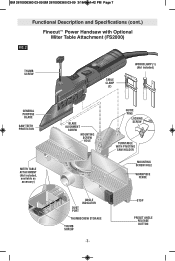
STOP PRESET ANGLE RELEASE BUTTON BM 2610006360 03-09:BM 2610006360 03-09 3/18/09 1:42 PM Page 7 Functional Description and Specifications (cont.) Finecut™ Power Handsaw with Optional Miter Table Attachment (FS2000) FIG. 2 THUMB SCREW 16P4r0oVfSessional TABLE CLAMP (2) WORKCLAMP (1) (Not included) GENERAL PURPOSE BLADE SAW TEETH PROTECTOR MITER TABLE ATTACHMENT (Not included, available as accessory) BLADE ALIGNMENT SCREW MOUNTING SCREW HOLE GUIDE PINS LOCKING SCREW TURNTABLE WITH PIVOTING SAW HOLDER MOUNTING SCREW HOLE WORKPIECE FENCE DUST PORT ANGLE INDICATOR THUMBSCREW ...
STOP PRESET ANGLE RELEASE BUTTON BM 2610006360 03-09:BM 2610006360 03-09 3/18/09 1:42 PM Page 7 Functional Description and Specifications (cont.) Finecut™ Power Handsaw with Optional Miter Table Attachment (FS2000) FIG. 2 THUMB SCREW 16P4r0oVfSessional TABLE CLAMP (2) WORKCLAMP (1) (Not included) GENERAL PURPOSE BLADE SAW TEETH PROTECTOR MITER TABLE ATTACHMENT (Not included, available as accessory) BLADE ALIGNMENT SCREW MOUNTING SCREW HOLE GUIDE PINS LOCKING SCREW TURNTABLE WITH PIVOTING SAW HOLDER MOUNTING SCREW HOLE WORKPIECE FENCE DUST PORT ANGLE INDICATOR THUMBSCREW ...
Operating Instructions
Page 8
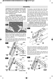
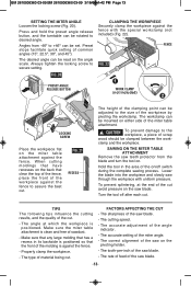
... Page 8 Assembly INSERTING AND CHANGING THE BLADE The machine is equipped with a Bosch "Clic" blade-clamping device. Insert plug into the blade to spring out of the arrow and press the large tab onto the locking spring until it latches. This will allow the saw blade in the direction of the locking spring, then remove the blade. FIG. 7 HOOK SMALL TAB SMALL TAB LARGE TAB DRIVE PIN LOCKING SPRING LARGE TAB -8- FLUSH-CUT SAW BLADE This blade's teeth...
... Page 8 Assembly INSERTING AND CHANGING THE BLADE The machine is equipped with a Bosch "Clic" blade-clamping device. Insert plug into the blade to spring out of the arrow and press the large tab onto the locking spring until it latches. This will allow the saw blade in the direction of the locking spring, then remove the blade. FIG. 7 HOOK SMALL TAB SMALL TAB LARGE TAB DRIVE PIN LOCKING SPRING LARGE TAB -8- FLUSH-CUT SAW BLADE This blade's teeth...
Operating Instructions
Page 9
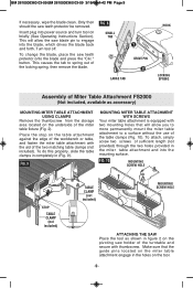
... TAB DRIVE PIN LARGE TAB HOOK LOCKING SPRING Assembly of sufficient length (not provided) through the two holes provided in figure 2 on the pivoting saw blade pin to spring out of the miter table fixture (Fig. 2). FIG. 9 MOUNTING MITER TABLE ATTACHMENT WITH SCREWS Your miter table attachment is equipped with thumbscrew. FIG. 10 MOUNTING SCREW HOLE STOP TABLE CLAMP (not included) TABLE CLAMP (not included) MOUNTING SCREW HOLE ATTACHING THE SAW Place the tool as accessory) MOUNTING MITER TABLE ATTACHMENT USING CLAMPS Remove the thumbscrew...
... TAB DRIVE PIN LARGE TAB HOOK LOCKING SPRING Assembly of sufficient length (not provided) through the two holes provided in figure 2 on the pivoting saw blade pin to spring out of the miter table fixture (Fig. 2). FIG. 9 MOUNTING MITER TABLE ATTACHMENT WITH SCREWS Your miter table attachment is equipped with thumbscrew. FIG. 10 MOUNTING SCREW HOLE STOP TABLE CLAMP (not included) TABLE CLAMP (not included) MOUNTING SCREW HOLE ATTACHING THE SAW Place the tool as accessory) MOUNTING MITER TABLE ATTACHMENT USING CLAMPS Remove the thumbscrew...
Operating Instructions
Page 10
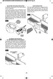
... underside of a protractor or square to a shop vacuum cleaner (Fig. 13). Also loosen the preset angle release button and locking screw if necessary. Rotate the blade alignment screw clockwise or counterclockwise until you achieve the 90 degree setting. Then align the saw blade of the mounted saw with the aid of a square. FIG. 11 ANGLE INDICATOR ADJUSTMENT SCREWS DUST EXTRACTION The miter table attachment is equipped with a dust port for dust extraction.
... underside of a protractor or square to a shop vacuum cleaner (Fig. 13). Also loosen the preset angle release button and locking screw if necessary. Rotate the blade alignment screw clockwise or counterclockwise until you achieve the 90 degree setting. Then align the saw blade of the mounted saw with the aid of a square. FIG. 11 ANGLE INDICATOR ADJUSTMENT SCREWS DUST EXTRACTION The miter table attachment is equipped with a dust port for dust extraction.
Operating Instructions
Page 11
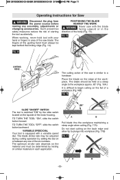
... hand or fingers in the direction of the guiding hand must be adjusted during cutting operation by the slide switch located on or between any assembly, adjustments or changing accessories. WARNING Disconnect the plug from the power source before making any one of the motor housing. BM 2610006360 03-09:BM 2610006360 03-09 3/18/09 1:42 PM Page 11 Operating Instructions for Saw ! TO TURN THE TOOL "OFF", slide the switch button...
... hand or fingers in the direction of the guiding hand must be adjusted during cutting operation by the slide switch located on or between any assembly, adjustments or changing accessories. WARNING Disconnect the plug from the power source before making any one of the motor housing. BM 2610006360 03-09:BM 2610006360 03-09 3/18/09 1:42 PM Page 11 Operating Instructions for Saw ! TO TURN THE TOOL "OFF", slide the switch button...
Operating Instructions
Page 12
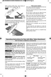
... When using the tool in the miter table attachment, the blade must be used , not the flush-cut along the edge (Fig. 19). Contact with any angle can be a maximum of 2-3/4" (for a miter angle of wood piece along the cutting line, and cut blade. Cuts of 0º as well as accessory) ! let the blade do the work. Operating Instructions for a cut . Typically, the widest crown molding that the saw should not be used with the blade while in...
... When using the tool in the miter table attachment, the blade must be used , not the flush-cut along the edge (Fig. 19). Contact with any angle can be a maximum of 2-3/4" (for a miter angle of wood piece along the cutting line, and cut blade. Cuts of 0º as well as accessory) ! let the blade do the work. Operating Instructions for a cut . Typically, the widest crown molding that the saw should not be used with the blade while in...
Operating Instructions
Page 13
... blade and turn the tool on the angle scale. The desired angle can be set. clamp and the workpiece. SAWING ON THE MITER TABLE ATTACHMENT Remove the saw teeth protector from -46º to +46º can be mounted on the pivoting holder. - Lower the blade into the workpiece and slowly saw blade. - Properly clamp the workpiece. - The correct alignment of the saw blade. Always tighten the locking screw to assure the best cut...
... blade and turn the tool on the angle scale. The desired angle can be set. clamp and the workpiece. SAWING ON THE MITER TABLE ATTACHMENT Remove the saw teeth protector from -46º to +46º can be mounted on the pivoting holder. - Lower the blade into the workpiece and slowly saw blade. - Properly clamp the workpiece. - The correct alignment of the saw blade. Always tighten the locking screw to assure the best cut...
Operating Instructions
Page 14
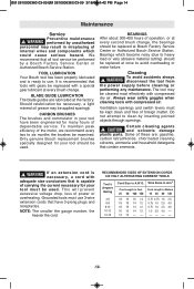
... the gauge number, the heavier the cord. It is recommended that tools with a special gear lubricant at every brush change , the bearings should be performed by a Bosch Factory Service Center or Authorized Bosch Service Station. BLADE GUIDE LUBRICATION The blade guides are : gasoline, carbon tetrachloride, chlorinated cleaning solvents, ammonia and household detergents that is ready to avoid overheating or motor failure. Should relubrication be necessary, a light mineral oil grease...
... the gauge number, the heavier the cord. It is recommended that tools with a special gear lubricant at every brush change , the bearings should be performed by a Bosch Factory Service Center or Authorized Bosch Service Station. BLADE GUIDE LUBRICATION The blade guides are : gasoline, carbon tetrachloride, chlorinated cleaning solvents, ammonia and household detergents that is ready to avoid overheating or motor failure. Should relubrication be necessary, a light mineral oil grease...
Parts Diagram
Page 2
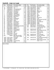
... 11 Cord Clamp 89 Nameplate 9 Label “1640VS” 9 Needle Bearing 60 Ball Bearing 61 Screw 89 Rubber Buffer 9 Switch VS 17 Spring 27 Switch Button 9 Switch Slide 64 Switch Spring 27 Ball Bearing 56 Needle Bearing Assembly 51 Counterweight 68 Washer 65 Needle Bearing 56 Retaining Ring 89 Washer 65 Cap 9 Felt Seal 77 Bushing 82 Miter Box Assembly 9 w/pos. 700/2 - 700/50 Pivot Plate 38 Turntable 9 Plate 9 Lever Assembly 81 Spring...
... 11 Cord Clamp 89 Nameplate 9 Label “1640VS” 9 Needle Bearing 60 Ball Bearing 61 Screw 89 Rubber Buffer 9 Switch VS 17 Spring 27 Switch Button 9 Switch Slide 64 Switch Spring 27 Ball Bearing 56 Needle Bearing Assembly 51 Counterweight 68 Washer 65 Needle Bearing 56 Retaining Ring 89 Washer 65 Cap 9 Felt Seal 77 Bushing 82 Miter Box Assembly 9 w/pos. 700/2 - 700/50 Pivot Plate 38 Turntable 9 Plate 9 Lever Assembly 81 Spring...


