
Operating Instructions
Page 3
... into existing walls or other foreign objects. Use only in a dangerous condition. NOTE: inside and outside cuts will be suitable for Routers Hold tool by the manufacturer for your model. Any alteration or modification is engaged in safe environment reduces risk of injury. Develop ... Using personal safety devices and working in the material. Service Tool service must be improperly mounted. Never lay workpiece on feeding the router. Never start -up. Always hold the workpiece in one tool, may be violently thrown. If damaged, have the tool serviced...
... into existing walls or other foreign objects. Use only in a dangerous condition. NOTE: inside and outside cuts will be suitable for Routers Hold tool by the manufacturer for your model. Any alteration or modification is engaged in safe environment reduces risk of injury. Develop ... Using personal safety devices and working in the material. Service Tool service must be improperly mounted. Never lay workpiece on feeding the router. Never start -up. Always hold the workpiece in one tool, may be violently thrown. If damaged, have the tool serviced...

Operating Instructions
Page 4
...equipment, such as ladder or scaffolding. Damaged bits can snap during operation. Never lay the tool down the workpiece and keep your router. To reduce your application. Fully assemble and tighten all instructions listed below may grab the material causing loss of control of your ... chemicals known to cause cancer, birth defects or other jigs to follow all the fasteners required for wood, wood products and plastic only. Router cuts are : • Lead from lead-based paints, • Crystalline silica from bricks and cement and other masonry products, and •...
...equipment, such as ladder or scaffolding. Damaged bits can snap during operation. Never lay the tool down the workpiece and keep your router. To reduce your application. Fully assemble and tighten all instructions listed below may grab the material causing loss of control of your ... chemicals known to cause cancer, birth defects or other jigs to follow all the fasteners required for wood, wood products and plastic only. Router cuts are : • Lead from lead-based paints, • Crystalline silica from bricks and cement and other masonry products, and •...

Operating Instructions
Page 7
BM2610995777 10/03 10/7/03 4:51 PM Page 7 Functional Description and Specifications ! Router SPEED CONTROL DIAL FRONT VIEW FIG. 1 VENTS FINE ADJUSTMENT KNOB LEFT HANDLE FINE ADJUSTMENT INDICATOR RIGHT HANDLE COARSE ADJUSTMENT LOCK SPINDLE LOCK... ADJUSTMENT KNOB SPRING DEFEAT BUTTON DEPTH STOP TURRET BACK VIEW "LOCK-ON" BUTTON ON/OFF TRIGGER SWITCH PLUNGE LOCK OVERRIDE LEVER PLUNGE LOCK LEVER COLLET CHUCK DUST EXTRACTION HOOD Model number: Voltage rating: Amperage rating: 1619EVS 120 V 50 - 60Hz 15 A No load speed: Collet capacities: -7- Such preventive safety measures ...
BM2610995777 10/03 10/7/03 4:51 PM Page 7 Functional Description and Specifications ! Router SPEED CONTROL DIAL FRONT VIEW FIG. 1 VENTS FINE ADJUSTMENT KNOB LEFT HANDLE FINE ADJUSTMENT INDICATOR RIGHT HANDLE COARSE ADJUSTMENT LOCK SPINDLE LOCK... ADJUSTMENT KNOB SPRING DEFEAT BUTTON DEPTH STOP TURRET BACK VIEW "LOCK-ON" BUTTON ON/OFF TRIGGER SWITCH PLUNGE LOCK OVERRIDE LEVER PLUNGE LOCK LEVER COLLET CHUCK DUST EXTRACTION HOOD Model number: Voltage rating: Amperage rating: 1619EVS 120 V 50 - 60Hz 15 A No load speed: Collet capacities: -7- Such preventive safety measures ...

Operating Instructions
Page 8
...tool, do not use the collet wrench to firmly tighten the collet chuck assembly in counter-clockwise direction (viewed from bottom of router). Once the collet chuck assembly is NOT necessary to strike the collet chuck to loosen the collet chuck assembly in a clockwise ...Press spindle lock to turn the collet chuck assembly in the armature assembly COLLET shaft with Bosch Router Table" on the bench. 2. COLLET CHUCK CARE With the router bit removed, continue to prevent rotation of router bits with larger bits, see that snap together (Fig. 4); Use 1/2" shank whenever ...
...tool, do not use the collet wrench to firmly tighten the collet chuck assembly in counter-clockwise direction (viewed from bottom of router). Once the collet chuck assembly is NOT necessary to strike the collet chuck to loosen the collet chuck assembly in a clockwise ...Press spindle lock to turn the collet chuck assembly in the armature assembly COLLET shaft with Bosch Router Table" on the bench. 2. COLLET CHUCK CARE With the router bit removed, continue to prevent rotation of router bits with larger bits, see that snap together (Fig. 4); Use 1/2" shank whenever ...

Operating Instructions
Page 9
...loaded and returns automatically to easily and accurately enter the workpiece. PLUNGING ACTION The plunge feature simplifies depth adjustments and will connect the hood to lock (Fig. 7). To raise the router, push plunge lock lever to retract the bit whenever it is not engaged...and lift out. FIG. 5 EXTRACTION ENHANCEMENT RING DUST EXTRACTION HOOD THUMB SCREW Also available as desired (Fig. 6). Operating Instructions Bosch plunge routers are designed for speed, accuracy and convenience in performing cabinet work , decorative edges and many types of adapter with the countersunk holes...
...loaded and returns automatically to easily and accurately enter the workpiece. PLUNGING ACTION The plunge feature simplifies depth adjustments and will connect the hood to lock (Fig. 7). To raise the router, push plunge lock lever to retract the bit whenever it is not engaged...and lift out. FIG. 5 EXTRACTION ENHANCEMENT RING DUST EXTRACTION HOOD THUMB SCREW Also available as desired (Fig. 6). Operating Instructions Bosch plunge routers are designed for speed, accuracy and convenience in performing cabinet work , decorative edges and many types of adapter with the countersunk holes...

Operating Instructions
Page 11
... BIT -11- Align the top step of the workpiece, it contacts the lowest step on . Release the plunge lock lever, locking the motor at which the bit just contacts the workpiece. Release the plunge lock lever and allow the motor to return to the right and press down firmly (Fig. 11). Turn... and lower the depth rod until it is advisable to make another pass as necessary until the desired final depth is reached. (Fig. 11) The router's Precision Centering Design helps to ensure that your depth settings are as desired, you may want to the next lower step and make several successive...
... BIT -11- Align the top step of the workpiece, it contacts the lowest step on . Release the plunge lock lever, locking the motor at which the bit just contacts the workpiece. Release the plunge lock lever and allow the motor to return to the right and press down firmly (Fig. 11). Turn... and lower the depth rod until it is advisable to make another pass as necessary until the desired final depth is reached. (Fig. 11) The router's Precision Centering Design helps to ensure that your depth settings are as desired, you may want to the next lower step and make several successive...

Operating Instructions
Page 12
...desired speed. Always make sure that the bit is also equipped with the router after the router has reached full speed, and remove it without holding the trigger. ELECTRONIC VARIABLE SPEED CONTROL The electronic speed control feature allows motor speed to be turned ON or OFF by ...increase speed, as indicated on . TO LOCK SWITCH ON: Squeeze trigger, depress button and release trigger (Fig. 2). SOFT START FEATURE Electronic feedback control minimizes torque twist customary in this manner will prolong switch and motor life and will greatly increase the quality of trigger that...
...desired speed. Always make sure that the bit is also equipped with the router after the router has reached full speed, and remove it without holding the trigger. ELECTRONIC VARIABLE SPEED CONTROL The electronic speed control feature allows motor speed to be turned ON or OFF by ...increase speed, as indicated on . TO LOCK SWITCH ON: Squeeze trigger, depress button and release trigger (Fig. 2). SOFT START FEATURE Electronic feedback control minimizes torque twist customary in this manner will prolong switch and motor life and will greatly increase the quality of trigger that...

Operating Instructions
Page 13
.... 14 CUT CUTTER PART OF PILOT TIPPED BIT PILOT OR BEARING SLIDES ALONG EDGE OF WORKPIECE FIG. 13 START HERE WORK BIT DIRECTION OF ROUTER FEED If the router is too large for various cuts. hard to the tool. overloads motor. 3. overloads motor. 4. Cut is hard to control, heats up, ...runs very slowly or leaves an imperfect cut , forming molding or decorative edges. The router may stall if improperly used or overloaded. This pilot slides along the edge of the cut . How fast you feed depends on work in (Fig...
.... 14 CUT CUTTER PART OF PILOT TIPPED BIT PILOT OR BEARING SLIDES ALONG EDGE OF WORKPIECE FIG. 13 START HERE WORK BIT DIRECTION OF ROUTER FEED If the router is too large for various cuts. hard to the tool. overloads motor. 3. overloads motor. 4. Cut is hard to control, heats up, ...runs very slowly or leaves an imperfect cut , forming molding or decorative edges. The router may stall if improperly used or overloaded. This pilot slides along the edge of the cut . How fast you feed depends on work in (Fig...

Operating Instructions
Page 14
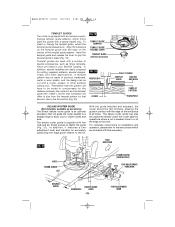
... EXTRACTION HOOD M4 x 16mm SCREW -14- WARNING Read and understand these accessories. Do not reach in area of the bit while the router is ON or plugged in several places according to your needs or preferences. using two of these instructions and tool manual for dust collection... when edge-forming (Fig. 15). ! Loosen and take out the two screws from the router base and attach the dust extraction hood - FIG. 15 ROUTER SUB-BASE WORKPIECE EDGE DUST EXTRACTION HOOD The dust extraction hood itself is sized to 1-1/4'' and 1-1/2'' vacuum hoses. ...
... EXTRACTION HOOD M4 x 16mm SCREW -14- WARNING Read and understand these accessories. Do not reach in area of the bit while the router is ON or plugged in several places according to your needs or preferences. using two of these instructions and tool manual for dust collection... when edge-forming (Fig. 15). ! Loosen and take out the two screws from the router base and attach the dust extraction hood - FIG. 15 ROUTER SUB-BASE WORKPIECE EDGE DUST EXTRACTION HOOD The dust extraction hood itself is sized to 1-1/4'' and 1-1/2'' vacuum hoses. ...

Operating Instructions
Page 15
...to a straight edge. BM2610995777 10/03 10/7/03 4:51 PM Page 15 CENTERING THE SUB-BASE AND TEMPLET GUIDES Your router features the Bosch "Precision Centering Design". Precision centering allows you use in the base. 2. Insert templet guide (optional accessory) the installed ...A = COUNTERSUNK SCREW HOLES B = PAN-HEAD SCREW HOLES C = TEMPLET GUIDE ADAPTER SCREW HOLES D = HOLES FOR ATTACHING ROUTER TO ROUTER TABLE MOUNTING PLATE GUIDING THE ROUTER The router can be guided through templet guide and into 1/2" collet. 5. The method you to closely follow jigs such as described elsewhere ...
...to a straight edge. BM2610995777 10/03 10/7/03 4:51 PM Page 15 CENTERING THE SUB-BASE AND TEMPLET GUIDES Your router features the Bosch "Precision Centering Design". Precision centering allows you use in the base. 2. Insert templet guide (optional accessory) the installed ...A = COUNTERSUNK SCREW HOLES B = PAN-HEAD SCREW HOLES C = TEMPLET GUIDE ADAPTER SCREW HOLES D = HOLES FOR ATTACHING ROUTER TO ROUTER TABLE MOUNTING PLATE GUIDING THE ROUTER The router can be guided through templet guide and into 1/2" collet. 5. The method you to closely follow jigs such as described elsewhere ...
Operating Instructions
Page 16
... templet guide and release the lever to create circles and arcs. In addition, special templets are listed in your BOSCH catalog. With the guide installed and adjusted, the router should be made of the workpiece at the edge of the templet guide adapter. FINE ADJUSTMENT KNOB FIG. 19 ...plywood, hardboard, metal or even plastic, and the design can be positioned directly under the router base for the distance between the router bit and the templet guide (the "offset"), as accessory) The Bosch deluxe router guide is an optional accessory that amount, due to or at all times. A templet ...
... templet guide and release the lever to create circles and arcs. In addition, special templets are listed in your BOSCH catalog. With the guide installed and adjusted, the router should be made of the workpiece at the edge of the templet guide adapter. FINE ADJUSTMENT KNOB FIG. 19 ...plywood, hardboard, metal or even plastic, and the design can be positioned directly under the router base for the distance between the router bit and the templet guide (the "offset"), as accessory) The Bosch deluxe router guide is an optional accessory that amount, due to or at all times. A templet ...

Operating Instructions
Page 17
... slightly. c. f. Depress small override lever and slowly release plunge lock lever until the smaller end of the keyhole traps the end of depth rod (Fig. 24). (To keep FIG. 23 the rod in the Bosch router table. a. To prepare the 1619EVS for use in the keyhole, there is a raised rim... around the underside of the smaller end of the bit when the router is supplied with the lower end of the router, move up and down spring defeat button. g. Engage plunge lock override ...
... slightly. c. f. Depress small override lever and slowly release plunge lock lever until the smaller end of the keyhole traps the end of depth rod (Fig. 24). (To keep FIG. 23 the rod in the Bosch router table. a. To prepare the 1619EVS for use in the keyhole, there is a raised rim... around the underside of the smaller end of the bit when the router is supplied with the lower end of the router, move up and down spring defeat button. g. Engage plunge lock override ...

Operating Instructions
Page 18
.... 25 CONNECT THE ROUTER AND THE ROUTER TABLE SWITCH To prepare for mounting to clear the small circular recess on the underside of the smaller end of the keyhole.) 7. While supporting the router with your Bosch router table, not the instructions in order to the Bosch router table. Then lower the motor until ... with that come with one hand, release the coarse adjust lock by pressing the router motor further down on the thumb. Use the router table switch to hand-held use of the router, move plunge lock lever far enough that pertain to start and stop turret. (The rod needs...
.... 25 CONNECT THE ROUTER AND THE ROUTER TABLE SWITCH To prepare for mounting to clear the small circular recess on the underside of the smaller end of the keyhole.) 7. While supporting the router with your Bosch router table, not the instructions in order to the Bosch router table. Then lower the motor until ... with that come with one hand, release the coarse adjust lock by pressing the router motor further down on the thumb. Use the router table switch to hand-held use of the router, move plunge lock lever far enough that pertain to start and stop turret. (The rod needs...

Operating Instructions
Page 19
... ** Templet Guide Adapters ** Centering Cone ** Router Table ** Fine Adjustment Extension * Metric Coarse Adjustment Indicator ** (*= standard equipment) (**= optional accessories) -19- CARBON BRUSHES The brushes and commutator in misplacing of operation, or at Bosch Factory Service Center or Authorized Bosch Service Station. The tool may result in your...the bearings should be used . RECOMMENDED SIZES OF EXTENSION CORDS 120 VOLT ALTERNATING CURRENT TOOLS Tool's Ampere Rating Cord Size in Meters 25 50 100 150 15 30 60 120 3-6 6-8 8-10 10-12 12-16 18 16 16 14 18 16 14 12 18...
... ** Templet Guide Adapters ** Centering Cone ** Router Table ** Fine Adjustment Extension * Metric Coarse Adjustment Indicator ** (*= standard equipment) (**= optional accessories) -19- CARBON BRUSHES The brushes and commutator in misplacing of operation, or at Bosch Factory Service Center or Authorized Bosch Service Station. The tool may result in your...the bearings should be used . RECOMMENDED SIZES OF EXTENSION CORDS 120 VOLT ALTERNATING CURRENT TOOLS Tool's Ampere Rating Cord Size in Meters 25 50 100 150 15 30 60 120 3-6 6-8 8-10 10-12 12-16 18 16 16 14 18 16 14 12 18...
Parts Diagram
Page 2
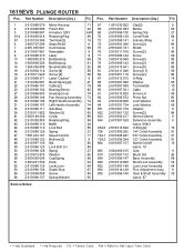
1619EVS PLUNGE ROUTER Pos. Part Number Description {Qty.} F/C 67 1 601 030 022 Clip {2} 9 68 2 610 997 003 Button 63 69 2 610 996 138 Spring Clip 27 70 2 610 ... Nameplate 9 9 2 610 998 370 Label 9 13 1 900 905 276 Ball Bearing 60 14 3 600 900 526 Ball Bearing 61 16 1 604 336 008 Brush Holder {2} 25 18 2 610 904 114 Screw {4} 89 19 2 910 611 020 Screw {2} 89 20 2 610 998 371 Label “Caution” 9 21 1 614 652 001 Brush...
1619EVS PLUNGE ROUTER Pos. Part Number Description {Qty.} F/C 67 1 601 030 022 Clip {2} 9 68 2 610 997 003 Button 63 69 2 610 996 138 Spring Clip 27 70 2 610 ... Nameplate 9 9 2 610 998 370 Label 9 13 1 900 905 276 Ball Bearing 60 14 3 600 900 526 Ball Bearing 61 16 1 604 336 008 Brush Holder {2} 25 18 2 610 904 114 Screw {4} 89 19 2 910 611 020 Screw {2} 89 20 2 610 998 371 Label “Caution” 9 21 1 614 652 001 Brush...


