
Operating Instructions
Page 7
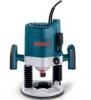
... the risk of starting the tool accidentally. BM2610995777 10/03 10/7/03 4:51 PM Page 7 Functional Description and Specifications ! Router SPEED CONTROL DIAL FRONT VIEW FIG. 1 VENTS FINE ADJUSTMENT KNOB LEFT HANDLE FINE ADJUSTMENT INDICATOR RIGHT HANDLE COARSE ADJUSTMENT LOCK SPINDLE...SPRING DEFEAT BUTTON DEPTH STOP TURRET BACK VIEW "LOCK-ON" BUTTON ON/OFF TRIGGER SWITCH PLUNGE LOCK OVERRIDE LEVER PLUNGE LOCK LEVER COLLET CHUCK DUST EXTRACTION HOOD Model number: Voltage rating: Amperage rating: 1619EVS 120 V 50 - 60Hz 15 A No load speed: Collet capacities: -7- BASE SUB-...
... the risk of starting the tool accidentally. BM2610995777 10/03 10/7/03 4:51 PM Page 7 Functional Description and Specifications ! Router SPEED CONTROL DIAL FRONT VIEW FIG. 1 VENTS FINE ADJUSTMENT KNOB LEFT HANDLE FINE ADJUSTMENT INDICATOR RIGHT HANDLE COARSE ADJUSTMENT LOCK SPINDLE...SPRING DEFEAT BUTTON DEPTH STOP TURRET BACK VIEW "LOCK-ON" BUTTON ON/OFF TRIGGER SWITCH PLUNGE LOCK OVERRIDE LEVER PLUNGE LOCK LEVER COLLET CHUCK DUST EXTRACTION HOOD Model number: Voltage rating: Amperage rating: 1619EVS 120 V 50 - 60Hz 15 A No load speed: Collet capacities: -7- BASE SUB-...

Operating Instructions
Page 9
...7). Do not use both hoods at any time. Operating Instructions Bosch plunge routers are designed for speed, accuracy and convenience in sub-base. To lower, push plunge lock lever to the left , release pressure on router and the router will allow the cutting bit to easily and accurately enter the... the sub-base, and align the two threaded holes in freehand routing. PLUNGING ACTION The plunge feature simplifies depth adjustments and will automatically retract the bit from the workpiece. To raise the router, push plunge lock lever to the left , apply downward pressure until you to accomplish...
...7). Do not use both hoods at any time. Operating Instructions Bosch plunge routers are designed for speed, accuracy and convenience in sub-base. To lower, push plunge lock lever to the left , release pressure on router and the router will allow the cutting bit to easily and accurately enter the... the sub-base, and align the two threaded holes in freehand routing. PLUNGING ACTION The plunge feature simplifies depth adjustments and will automatically retract the bit from the workpiece. To raise the router, push plunge lock lever to the left , apply downward pressure until you to accomplish...

Operating Instructions
Page 11
Turn the coarse depth indicator until router bit just contacts the level surface the router is the "zero" position, which indicates the point at this position. (Fig. 10) 3. Release the plunge lock lever and allow the motor to return to the right and press down firmly (Fig. 11). To be ...TURRET REFERENCE MARK COARSE ADJUSTMENT LOCK DEPTH ROD DEPTH STOP TURRET BIT -11- BM2610995777 10/03 10/7/03 4:51 PM Page 11 MAKING PROGESSIVELY DEEPER PLUNGE CUTS When making a single deep cut: 1. Align the lowest step of the workpiece, it contacts the lowest step on . Loosen the coarse...
Turn the coarse depth indicator until router bit just contacts the level surface the router is the "zero" position, which indicates the point at this position. (Fig. 10) 3. Release the plunge lock lever and allow the motor to return to the right and press down firmly (Fig. 11). To be ...TURRET REFERENCE MARK COARSE ADJUSTMENT LOCK DEPTH ROD DEPTH STOP TURRET BIT -11- BM2610995777 10/03 10/7/03 4:51 PM Page 11 MAKING PROGESSIVELY DEEPER PLUNGE CUTS When making a single deep cut: 1. Align the lowest step of the workpiece, it contacts the lowest step on . Loosen the coarse...

Operating Instructions
Page 17
.... BM2610995777 10/03 10/7/03 4:51 PM Page 17 Preparation For Use With Bosch Router Table Your router is uniquely suited for table mounting, do the following: HOUSING FIG. 22 PLUNGE LOCK OVERRIDE LEVER PLUNGE LOCK LEVER d. f. Connect the depth rod to the depth stop turret by ... Bosch router table. The motor is now free to adjust the height of the router keeps the depth rod inside the raised SPRING DEFEAT BUTTON rim.) Note: When the router motor is now disengaged. b. e. To prepare the 1619EVS for use in place with coarse adjustment lock. Plunge the router ...
.... BM2610995777 10/03 10/7/03 4:51 PM Page 17 Preparation For Use With Bosch Router Table Your router is uniquely suited for table mounting, do the following: HOUSING FIG. 22 PLUNGE LOCK OVERRIDE LEVER PLUNGE LOCK LEVER d. f. Connect the depth rod to the depth stop turret by ... Bosch router table. The motor is now free to adjust the height of the router keeps the depth rod inside the raised SPRING DEFEAT BUTTON rim.) Note: When the router motor is now disengaged. b. e. To prepare the 1619EVS for use in place with coarse adjustment lock. Plunge the router ...

Operating Instructions
Page 18
... ROUTER TO MOUNTING PLATE 1. Make sure the router switch and the router table switch are both turned off. 2. Remove the router table mounting plate and reattach the router's sub-base. 4. The router will immediately put strong pressure on the thumb. WARNING override lever springs free, the plunge lock...optional fine adjustment knob extension onto the end of the fine adjustment knob. (Fig. 25) FIG. 25 CONNECT THE ROUTER AND THE ROUTER TABLE SWITCH To prepare for mounting to the Bosch router table. FEEDING THE WORKPIECE Follow the instructions that the small override lever can now be...
... ROUTER TO MOUNTING PLATE 1. Make sure the router switch and the router table switch are both turned off. 2. Remove the router table mounting plate and reattach the router's sub-base. 4. The router will immediately put strong pressure on the thumb. WARNING override lever springs free, the plunge lock...optional fine adjustment knob extension onto the end of the fine adjustment knob. (Fig. 25) FIG. 25 CONNECT THE ROUTER AND THE ROUTER TABLE SWITCH To prepare for mounting to the Bosch router table. FEEDING THE WORKPIECE Follow the instructions that the small override lever can now be...
Parts Diagram
Page 2
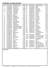
.... 9 855 2 610 996 149 Gear & Shaft Assembly 32 w/pos. 87 + = Not Illustrated * = As Required F/C = Failure Code AW = Refer to AW Labor Time Chart 1619EVS PLUNGE ROUTER Pos. Part Number Description {Qty.} F/C 1 2 610 996 079 Motor Housing 71 2 2 610 996 096 Field 120V 22 3 2 610 996 097 Armature 120V AW 3/14 2 916... 9 9 2 610 998 370 Label 9 13 1 900 905 276 Ball Bearing 60 14 3 600 900 526 Ball Bearing 61 16 1 604 336 008 Brush Holder {2} 25 18 2 610 904 114 Screw {4} 89 19 2 910 611 020 Screw {2} 89 20 2 610 998 371 Label “Caution” 9 21 1 614 652 001...
.... 9 855 2 610 996 149 Gear & Shaft Assembly 32 w/pos. 87 + = Not Illustrated * = As Required F/C = Failure Code AW = Refer to AW Labor Time Chart 1619EVS PLUNGE ROUTER Pos. Part Number Description {Qty.} F/C 1 2 610 996 079 Motor Housing 71 2 2 610 996 096 Field 120V 22 3 2 610 996 097 Armature 120V AW 3/14 2 916... 9 9 2 610 998 370 Label 9 13 1 900 905 276 Ball Bearing 60 14 3 600 900 526 Ball Bearing 61 16 1 604 336 008 Brush Holder {2} 25 18 2 610 904 114 Screw {4} 89 19 2 910 611 020 Screw {2} 89 20 2 610 998 371 Label “Caution” 9 21 1 614 652 001...


