
U8668 user's manual
Page 2
...: IDE1/IDE2 16 4-5. Wake On LAN Header: JWOL1 16 4-7. CNR Code Primary/Secondary Selection: JCODECSEL..........17 4-9. Layout of Contents Notice 1 Mainboard Features 2 1. Component Index 8 3. ATX 20-pin Power Connector: JATXPWR1 15 4-3. Package Contents 6 2. System Fan Header: JSFAN1 (Optional ... 1-2. CPU Configuration 9 3-1. ATX 12V Power Connector: JATXPWR2 15 4-4. Floppy Disk Connector: FDD1 16 4-6. Table of U8668 7 2-2. CPU Fan Header: JCFAN1 10 3-3. Features Introduction 2 1-1. Clear CMOS Jumper: JCMOS1 17 4-8. Front USB Header: JUSB3 (with USB1.0 spe ...
...: IDE1/IDE2 16 4-5. Wake On LAN Header: JWOL1 16 4-7. CNR Code Primary/Secondary Selection: JCODECSEL..........17 4-9. Layout of Contents Notice 1 Mainboard Features 2 1. Component Index 8 3. ATX 20-pin Power Connector: JATXPWR1 15 4-3. Package Contents 6 2. System Fan Header: JSFAN1 (Optional ... 1-2. CPU Configuration 9 3-1. ATX 12V Power Connector: JATXPWR2 15 4-4. Floppy Disk Connector: FDD1 16 4-6. Table of U8668 7 2-2. CPU Fan Header: JCFAN1 10 3-3. Features Introduction 2 1-1. Clear CMOS Jumper: JCMOS1 17 4-8. Front USB Header: JUSB3 (with USB1.0 spe ...
U8668 user's manual
Page 4
U8668 Features: 1.Contains on board I/O facilities that include two serial ports, a parallel port, a PS/2 mouse port, a PS/2 keyboard port, audio ports, USB ports and a game port. 2.... IDE devices such as Windows NT, Windows 2000, Windows ME, Windows XP, Novell, LINUX and SCO UNIX. 1-1 Chapter 1 Motherboard Description Notice Introduction of system This mainboard is designed to take advantage of its predecessors, this mainboard continues a commitment to provide you with the ultimate solution in data processing.
U8668 Features: 1.Contains on board I/O facilities that include two serial ports, a parallel port, a PS/2 mouse port, a PS/2 keyboard port, audio ports, USB ports and a game port. 2.... IDE devices such as Windows NT, Windows 2000, Windows ME, Windows XP, Novell, LINUX and SCO UNIX. 1-1 Chapter 1 Motherboard Description Notice Introduction of system This mainboard is designed to take advantage of its predecessors, this mainboard continues a commitment to provide you with the ultimate solution in data processing.
U8668 user's manual
Page 5
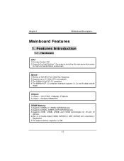
... devices 2.Supports 200MHz, 266MHz DDR SDRAM devices. 3.Supports 64Mb, 128Mb, 256Mb and 512Mb technologies for high-end workstations and servers. Features Introduction 1-1. Chapter 1 Motherboard Description Mainboard Features 1. Speed: 1.Runing at 400 MHz Front Side Bus frequency. 2.Supports up to 2.4 GHz CPU core speeds. 3.The 33MHz 32 bit PCI 2.2 compliant. 4.The 66MHz...
... devices 2.Supports 200MHz, 266MHz DDR SDRAM devices. 3.Supports 64Mb, 128Mb, 256Mb and 512Mb technologies for high-end workstations and servers. Features Introduction 1-1. Chapter 1 Motherboard Description Mainboard Features 1. Speed: 1.Runing at 400 MHz Front Side Bus frequency. 2.Supports up to 2.4 GHz CPU core speeds. 3.The 33MHz 32 bit PCI 2.2 compliant. 4.The 66MHz...
U8668 user's manual
Page 10
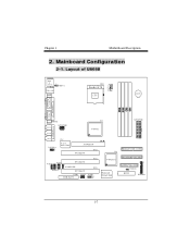
Chapter 1 Motherboard Description 2. Mainboard Configuration 2-1. U19 VT8233A Winbond W83697HF SECONDARY IDE CONN. 24 23 FLOPPY DISK CONN. 1 JCMOS1 BIOS 21 JPANEL1 1-7 Layout of U8668 JKBMS1 K/B & Mouse 1 JLAN USB & LAN JCOM1 JKBV1 CPU1 Socket 478 CPU BAT1 COM1 Parallel Port VGA1 JPRNT1 JVGA1 J AT X P W R 2 SPKR-OUT LINE-IN U13 VT8751 J ...
Chapter 1 Motherboard Description 2. Mainboard Configuration 2-1. U19 VT8233A Winbond W83697HF SECONDARY IDE CONN. 24 23 FLOPPY DISK CONN. 1 JCMOS1 BIOS 21 JPANEL1 1-7 Layout of U8668 JKBMS1 K/B & Mouse 1 JLAN USB & LAN JCOM1 JKBV1 CPU1 Socket 478 CPU BAT1 COM1 Parallel Port VGA1 JPRNT1 JVGA1 J AT X P W R 2 SPKR-OUT LINE-IN U13 VT8751 J ...

U8668 user's manual
Page 19
... IDE Connector) The IDE2 controller can connect a Master and a Slave drive. IDE1 can also support a Master and a Slave drive. Hard Disk Connectors: IDE1/IDE2 This mainboard has a 32-bit Enhanced PCI IDE Controller that supports 360K, 720K, 1.2M, 1.44M and 2.88M floppy disk types. This connector supports the provided floppy drive...
... IDE Connector) The IDE2 controller can connect a Master and a Slave drive. IDE1 can also support a Master and a Slave drive. Hard Disk Connectors: IDE1/IDE2 This mainboard has a 32-bit Enhanced PCI IDE Controller that supports 360K, 720K, 1.2M, 1.44M and 2.88M floppy disk types. This connector supports the provided floppy drive...
U8668 user's manual
Page 23
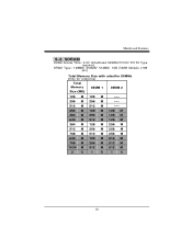
DRAM Type: 128MB/ 256MB/ 512MB/ 1GB DIMM Module (168 pin) Total Memory Size with unbuffer DIMMs (Only for reference) Total Memory Size (MB) DIMM 1 DIMM 2 128 M 128 M ---- 256 M 256 M ---- 512 M 512 M ---- 256 M 128 M 128 M 384 M 256 M 128 M 640 M 512 M 128 M 384 M 128 M 256 M 512 M 256 M 256 M 768 M 512 M 256 M 640 M 128 M 512 M 768 M 256 M 512 M 1024 M 512 M 512 M 2 G 1 G 1 G 20 SDRAM DRAM Access Time: 3.3V Unbuffered SDRAM PC100/ PC133 Type required. Mainboard Features 5-2.
DRAM Type: 128MB/ 256MB/ 512MB/ 1GB DIMM Module (168 pin) Total Memory Size with unbuffer DIMMs (Only for reference) Total Memory Size (MB) DIMM 1 DIMM 2 128 M 128 M ---- 256 M 256 M ---- 512 M 512 M ---- 256 M 128 M 128 M 384 M 256 M 128 M 640 M 512 M 128 M 384 M 128 M 256 M 512 M 256 M 256 M 768 M 512 M 256 M 640 M 128 M 512 M 768 M 256 M 512 M 1024 M 512 M 512 M 2 G 1 G 1 G 20 SDRAM DRAM Access Time: 3.3V Unbuffered SDRAM PC100/ PC133 Type required. Mainboard Features 5-2.
U8668 user's manual
Page 24
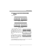
How to install DDR/SDRAM DIMM Module DDR SDRAM: Single Sided DIMM Double Sided DIMM 1. The DDR DIMM socket has a " Plastic Safety Tab", and the DDR DIMM memory module has an Asymmetrical notch", so the DDR DIMM memory module can only fit into the place. 3. The Mounting Holes and plastic tabs should fit over the edge and hold the DDR DIMM memory modules in one direction. 2. Push the tabs out. Mainboard Features 5-3. Insert the DDR DIMM memory modules into the socket at a 90-degree angle, then push down vertically so that it will fit into the slot in place. 21
How to install DDR/SDRAM DIMM Module DDR SDRAM: Single Sided DIMM Double Sided DIMM 1. The DDR DIMM socket has a " Plastic Safety Tab", and the DDR DIMM memory module has an Asymmetrical notch", so the DDR DIMM memory module can only fit into the place. 3. The Mounting Holes and plastic tabs should fit over the edge and hold the DDR DIMM memory modules in one direction. 2. Push the tabs out. Mainboard Features 5-3. Insert the DDR DIMM memory modules into the socket at a 90-degree angle, then push down vertically so that it will fit into the slot in place. 21
U8668 user's manual
Page 25
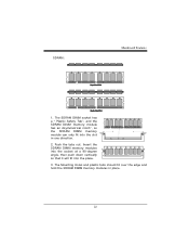
Push the tabs out. SDRAM: Mainboard Features 1. The Mounting Holes and plastic tabs should fit over the edge and hold the SDRAM DIMM memory modules in one direction. 2. Insert the SDRAM DIMM memory modules into the socket at a 90-degree angle, then push down vertically so that it will fit into the slot in place. 22 The SDRAM DIMM socket has a " Plastic Safety Tab", and the SDRAM DIMM memory module has an Asymmetrical notch", so the SDRAM DIMM memory module can only fit into the place. 3.
Push the tabs out. SDRAM: Mainboard Features 1. The Mounting Holes and plastic tabs should fit over the edge and hold the SDRAM DIMM memory modules in one direction. 2. Insert the SDRAM DIMM memory modules into the socket at a 90-degree angle, then push down vertically so that it will fit into the slot in place. 22 The SDRAM DIMM socket has a " Plastic Safety Tab", and the SDRAM DIMM memory module has an Asymmetrical notch", so the SDRAM DIMM memory module can only fit into the place. 3.
U8668 user's manual
Page 26
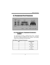
...: JKBMS1 The motherboard provides a standard PS/2 mouse / Keyboard mini DIN connector for attaching a PS/2 mouse. You can plug a PS/2 mouse / Keyboard directly into this connector. Mainboard Features 6. Peripheral Port Features JKBMS1 PS/2 JUSBLAN1 Mouse LAN JPRNT1 Parallel JAUD_GAME Game Port PS/2 Keyboard USB COM1 JCOM1 VGA1 Speaker Out Line In Mic...
...: JKBMS1 The motherboard provides a standard PS/2 mouse / Keyboard mini DIN connector for attaching a PS/2 mouse. You can plug a PS/2 mouse / Keyboard directly into this connector. Mainboard Features 6. Peripheral Port Features JKBMS1 PS/2 JUSBLAN1 Mouse LAN JPRNT1 Parallel JAUD_GAME Game Port PS/2 Keyboard USB COM1 JCOM1 VGA1 Speaker Out Line In Mic...
U8668 user's manual
Page 27
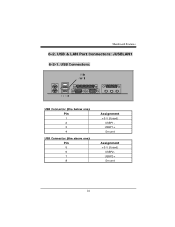
USB & LAN Port Connectors: JUSBLAN1 6-2-1. Mainboard Features 6-2. USB Connectors: USB Connector (the below one) Pin 1 2 3 4 USB Connector (the above one) Pin 5 6 7 8 Assignment +5 V (fused) USBP1USBP1+ Ground Assignment +5 V (fused) USBP2USBP2+ Ground 24
USB & LAN Port Connectors: JUSBLAN1 6-2-1. Mainboard Features 6-2. USB Connectors: USB Connector (the below one) Pin 1 2 3 4 USB Connector (the above one) Pin 5 6 7 8 Assignment +5 V (fused) USBP1USBP1+ Ground Assignment +5 V (fused) USBP2USBP2+ Ground 24
U8668 user's manual
Page 28
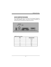
LAN Port Connector This connector allows you to connect to the Internet through a Local Area Network (LAN). You can set up the connection by entering account information provided by your ISP. Mainboard Features 6-2-2. LAN Port Connector Pin 9 10 11 12 13 14 Assignment VCC3 TD+ TDRD+ RDNC 25
LAN Port Connector This connector allows you to connect to the Internet through a Local Area Network (LAN). You can set up the connection by entering account information provided by your ISP. Mainboard Features 6-2-2. LAN Port Connector Pin 9 10 11 12 13 14 Assignment VCC3 TD+ TDRD+ RDNC 25
U8668 user's manual
Page 29
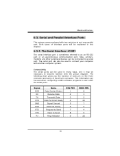
... Transmit Data Data Terminal Ready Signal Ground Data Set Ready Request to Send Clear to as an RS-232 port or an asynchronous communication port. Mainboard Features 6-3. Serial and Parallel Interface Ports This system comes equipped with the serial ports. Both types of the 25-pin connector. The Serial Interface: JCOM1...
... Transmit Data Data Terminal Ready Signal Ground Data Set Ready Request to Send Clear to as an RS-232 port or an asynchronous communication port. Mainboard Features 6-3. Serial and Parallel Interface Ports This system comes equipped with the serial ports. Both types of the 25-pin connector. The Serial Interface: JCOM1...
U8668 user's manual
Page 30
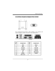
Mainboard Features 6-3-2Video Graphics Adapter Port: JVGA1 This motherboard has built in video facilities. Assignment Pin No. Assignment 1 Red 2 Green 3 Blue 4 NC 5 Ground 6 Ground 7 Ground 8 Ground 9 +5V 10 Ground 11 NC 12 DDC/Data 13 HSYNC 14 VSYNC 15 DDC/CLK 27 Your monitor will attach directly to JVGA1 connector on the motherboard. 5 1 15 11 JVGA1 Pin No.
Mainboard Features 6-3-2Video Graphics Adapter Port: JVGA1 This motherboard has built in video facilities. Assignment Pin No. Assignment 1 Red 2 Green 3 Blue 4 NC 5 Ground 6 Ground 7 Ground 8 Ground 9 +5V 10 Ground 11 NC 12 DDC/Data 13 HSYNC 14 VSYNC 15 DDC/CLK 27 Your monitor will attach directly to JVGA1 connector on the motherboard. 5 1 15 11 JVGA1 Pin No.
U8668 user's manual
Page 31
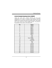
Sometimes called centronics port, the parallel port is almost exclusively used with printers. The pinout for the parallel port are shown in the table below. Mainboard Features 6-3-3. Parallel Interface Port: JPRNT1 Unlike the serial ports, parallel interface port has been standardized and should not present any difficulty interfacing peripherals to your ...
Sometimes called centronics port, the parallel port is almost exclusively used with printers. The pinout for the parallel port are shown in the table below. Mainboard Features 6-3-3. Parallel Interface Port: JPRNT1 Unlike the serial ports, parallel interface port has been standardized and should not present any difficulty interfacing peripherals to your ...
U8668 user's manual
Page 32
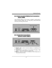
... connect speakers or headphones for playing computer games. Line In can be connected to connect a joystick or game pad for audio output. 2. Game/Joystick/MIDI 6-5. Mainboard Features 6-4. Audio Port Connectors: JSPKR1/JLIN1/JMIC1 Speaker Out Line In Mic In 1. Speaker Out is used to input sounds and voices. 29 Mic In...
... connect speakers or headphones for playing computer games. Line In can be connected to connect a joystick or game pad for audio output. 2. Game/Joystick/MIDI 6-5. Mainboard Features 6-4. Audio Port Connectors: JSPKR1/JLIN1/JMIC1 Speaker Out Line In Mic In 1. Speaker Out is used to input sounds and voices. 29 Mic In...
U8668 compatibility test report
Page 2
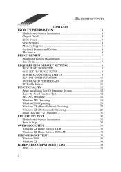
CONTENTS PRODUCT INFORMATION 4 Motherboard General Information 4 Chipset Details 4 BIOS Details 4 CPU Supports 4 Memory Supports 4 On-board Features and Devices 4 Mechanical 5 DESIGN REVIEW 7 Mainboard Voltage Measurement 7 Bus Clock 7 REQUIRED BIOS DEFAULT SETTINGS 8 BIOS FEATURES SETUP 8 CHIPSET FEATURES SETUP 8 POWER MANAGEMENT SETUP 9 PnP / PCI CONFIGURATION 10 INTEGRATED PERIPHERALS 10 PC ...
CONTENTS PRODUCT INFORMATION 4 Motherboard General Information 4 Chipset Details 4 BIOS Details 4 CPU Supports 4 Memory Supports 4 On-board Features and Devices 4 Mechanical 5 DESIGN REVIEW 7 Mainboard Voltage Measurement 7 Bus Clock 7 REQUIRED BIOS DEFAULT SETTINGS 8 BIOS FEATURES SETUP 8 CHIPSET FEATURES SETUP 8 POWER MANAGEMENT SETUP 9 PnP / PCI CONFIGURATION 10 INTEGRATED PERIPHERALS 10 PC ...

U8668 compatibility test report
Page 7
DESIGN REVIEW Mainboard Voltage Measurement Voltage List Battery Voltage Battery Current Voltage SPEC 3.0V 7uA Voltage Measured 3.09V 2.7uA +5V 5.0V+-5% 5.13 +12V -5V -12V 12.0V+-5% -5.0V+-5% -...
DESIGN REVIEW Mainboard Voltage Measurement Voltage List Battery Voltage Battery Current Voltage SPEC 3.0V 7uA Voltage Measured 3.09V 2.7uA +5V 5.0V+-5% 5.13 +12V -5V -12V 12.0V+-5% -5.0V+-5% -...