
Setup Manual
Page 5
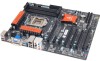
... signals out-put function. connection Board Size 230 (W) x 305 (L) mm OS Support Windows XP / Vista / 7 Biostar reserves the right to USB3.0 devices (by ASM1042) and USB2.0/USB1.X devices (by Z68. 3 TZ68A+ SPEC Clear CMOS Header x1 Restore CMOS data to factory default USB2.0 Connector x3 Each connector supports 2 front panel USB2.0 ports Consumer...
... signals out-put function. connection Board Size 230 (W) x 305 (L) mm OS Support Windows XP / Vista / 7 Biostar reserves the right to USB3.0 devices (by ASM1042) and USB2.0/USB1.X devices (by Z68. 3 TZ68A+ SPEC Clear CMOS Header x1 Restore CMOS data to factory default USB2.0 Connector x3 Each connector supports 2 front panel USB2.0 ports Consumer...

Setup Manual
Page 17
Wait for USB 2.0 Ports at Front Panel These headers allow user to "Pin 2-3 close ". 5. Load Optimal Defaults and save settings in CMOS. F_USB3 F_ USB1 F _US B 2 2 10 Pin Assignment 1 +5V (fused) 2 +5V (fused) 3 USB- 4 USB- 5 USB+ 6 USB+ 7 Ground 8 Ground 9 Key 10 NC 1 9 15 ... USB cable on the PC front panel, and also can be connected with internal USB devices, like USB card reader. TZ68A+ JCMOS1: Clear CMOS Header Placing the jumper on pin2-3 allows user to avoid damaging the motherboard. 13 Pin 1-2 Close: Normal Operation (default). 13 13 Pin 2-3 ...
Wait for USB 2.0 Ports at Front Panel These headers allow user to "Pin 2-3 close ". 5. Load Optimal Defaults and save settings in CMOS. F_USB3 F_ USB1 F _US B 2 2 10 Pin Assignment 1 +5V (fused) 2 +5V (fused) 3 USB- 4 USB- 5 USB+ 6 USB+ 7 Ground 8 Ground 9 Key 10 NC 1 9 15 ... USB cable on the PC front panel, and also can be connected with internal USB devices, like USB card reader. TZ68A+ JCMOS1: Clear CMOS Header Placing the jumper on pin2-3 allows user to avoid damaging the motherboard. 13 Pin 1-2 Close: Normal Operation (default). 13 13 Pin 2-3 ...
Setup Manual
Page 25
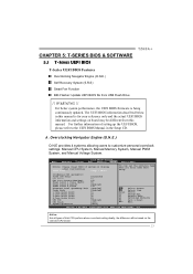
...] Enter +/F1 F3 F4 ESC Select Screen Select Item Select Change Opt. Main BIOS SETUP UTILITY Advanced Chipset Boot Security O.N.E Save & Exit Notice: Please Clear CMOS if system no display after overclocking Start Page [Page - For further information of Intel CPU perform above overclock setting ideally; General Help Optimized Defaults Save...
...] Enter +/F1 F3 F4 ESC Select Screen Select Item Select Change Opt. Main BIOS SETUP UTILITY Advanced Chipset Boot Security O.N.E Save & Exit Notice: Please Clear CMOS if system no display after overclocking Start Page [Page - For further information of Intel CPU perform above overclock setting ideally; General Help Optimized Defaults Save...

Setup Manual
Page 39
... cord and boot up the system. The CPU cooler surface is rotated normally. 3. Remove the power cord from power supply for seconds. 3. Clear the CMOS data. (See "Close CMOS Header: JCMOS1" section) 2. In this case, please double check: 1. Wait for seconds. 2. CPU fan is placed evenly with the CPU speed. Or you...
... cord and boot up the system. The CPU cooler surface is rotated normally. 3. Remove the power cord from power supply for seconds. 3. Clear the CMOS data. (See "Close CMOS Header: JCMOS1" section) 2. In this case, please double check: 1. Wait for seconds. 2. CPU fan is placed evenly with the CPU speed. Or you...
Setup Manual
Page 40
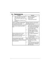
... 1. Back up the hard drive is Power LED does not shine; Screen message shows "Invalid Configuration" or "CMOS Failure." second hard drive. 2. Make sure power cable is extremely important. the securely plugged in the standard CMOS setup. Replace cable. Contact technical support. 2. System is in setup. Keyboard lights Using even pressure on...
... 1. Back up the hard drive is Power LED does not shine; Screen message shows "Invalid Configuration" or "CMOS Failure." second hard drive. 2. Make sure power cable is extremely important. the securely plugged in the standard CMOS setup. Replace cable. Contact technical support. 2. System is in setup. Keyboard lights Using even pressure on...