Update Manual
Page 1
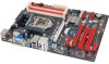
... DVD Driver. 2. Choose the location for your backup BIOS file in the system. BIOS update utility 1. A warning message will take several minutes, please be patient. 6. Installing BIOS Update Utility from www.biostar.com. While the system boots up and the full screen logo shows up to restart the computer.
... DVD Driver. 2. Choose the location for your backup BIOS file in the system. BIOS update utility 1. A warning message will take several minutes, please be patient. 6. Installing BIOS Update Utility from www.biostar.com. While the system boots up and the full screen logo shows up to restart the computer.
Update Manual
Page 2
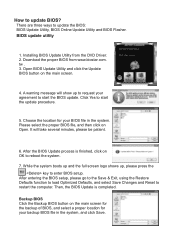
... download is completed. Click OK to start the online update procedure. 5. Then, the BIOS Update is completed, you to program (update) the BIOS or not. Installing BIOS Update Utility from the DVD Driver. 2. Please make sure the system is connected to the internet before using the Restore Defaults function to load...
... download is completed. Click OK to start the online update procedure. 5. Then, the BIOS Update is completed, you to program (update) the BIOS or not. Installing BIOS Update Utility from the DVD Driver. 2. Please make sure the system is connected to the internet before using the Restore Defaults function to load...

Setup Manual
Page 1
...in this publication, in part or in whole, is subject to provide reasonable protection against harmful interference in a residential installation. Duplication of a Class B digital device, pursuant to radio communications. The vendor makes no guarantee that interference will not be ...responsible for any purpose. TZ77B/TZ75B/T77 Setup Manual FCC Information and Copyright This equipment has been tested and found in a particular installation. This equipment generates, uses, and can radiate radio frequency energy and, if...
...in this publication, in part or in whole, is subject to provide reasonable protection against harmful interference in a residential installation. Duplication of a Class B digital device, pursuant to radio communications. The vendor makes no guarantee that interference will not be ...responsible for any purpose. TZ77B/TZ75B/T77 Setup Manual FCC Information and Copyright This equipment has been tested and found in a particular installation. This equipment generates, uses, and can radiate radio frequency energy and, if...

Setup Manual
Page 2
...Start 1 1.2 Package Checklist 1 1.3 Motherboard Features 2 1.4 Rear Panel Connectors 4 1.5 Motherboard Layout 5 Chapter 2: Hardware Installation 6 2.1 Installing Central Processing Unit (CPU 6 2.2 FAN Headers 8 2.3 Installing System Memory 9 2.4 Connectors and Slots 11 Chapter 3: Headers & Jumpers Setup 15 3.1 How to Setup Jumpers 15 3.2... & Software........... 27 5.1 T-Series UEFI BIOS 27 5.2 T-Series Software 30 Chapter 6: Useful Help 40 6.1 Driver Installation Note 40 6.2 Extra Information 41 6.3 AMI BIOS Post Code 42 6.4 Troubleshooting 44 Appendix: SPEC In Other Languages...
...Start 1 1.2 Package Checklist 1 1.3 Motherboard Features 2 1.4 Rear Panel Connectors 4 1.5 Motherboard Layout 5 Chapter 2: Hardware Installation 6 2.1 Installing Central Processing Unit (CPU 6 2.2 FAN Headers 8 2.3 Installing System Memory 9 2.4 Connectors and Slots 11 Chapter 3: Headers & Jumpers Setup 15 3.1 How to Setup Jumpers 15 3.2... & Software........... 27 5.1 T-Series UEFI BIOS 27 5.2 T-Series Software 30 Chapter 6: Useful Help 40 6.1 Driver Installation Note 40 6.2 Extra Information 41 6.3 AMI BIOS Post Code 42 6.4 Troubleshooting 44 Appendix: SPEC In Other Languages...

Setup Manual
Page 3
... should be 0 to 45 degrees Celsius. 1.2 PACKAGE CHECKLIST Serial ATA Cable X 4 Rear I/O Panel for choosing our product. CHAPTER 1: INTRODUCTION TZ77B/TZ75B/T77 1.1 BEFORE YOU START Thank you take the motherboard out from dangerous area, such as heat source, humid air and water. „... The operating temperatures of the board unless necessary. Before you start installing the motherboard, please make sure you follow the instructions below: „ Prepare a dry and stable working environment with sufficient lighting. „...
... should be 0 to 45 degrees Celsius. 1.2 PACKAGE CHECKLIST Serial ATA Cable X 4 Rear I/O Panel for choosing our product. CHAPTER 1: INTRODUCTION TZ77B/TZ75B/T77 1.1 BEFORE YOU START Thank you take the motherboard out from dangerous area, such as heat source, humid air and water. „... The operating temperatures of the board unless necessary. Before you start installing the motherboard, please make sure you follow the instructions below: „ Prepare a dry and stable working environment with sufficient lighting. „...

Setup Manual
Page 8
Step 1: Pull the socket locking lever out from the socket and then raise the lever up. When the CPU is removed, cover the Pin Cap on the empty socket to remove the pin cap. Remove Pin Cap before installation, and make good preservation for future use. The motherboard might equip with two different types of pin cap. Please refer below instruction to ensure pin legs won't be damaged. 2. Motherboard Manual CHAPTER 2: HARDWARE INSTALLATION 2.1 INSTALLING CENTRAL PROCESSING UNIT (CPU) Notice: 1. Step 2: Remove the Pin Cap. 6
Step 1: Pull the socket locking lever out from the socket and then raise the lever up. When the CPU is removed, cover the Pin Cap on the empty socket to remove the pin cap. Remove Pin Cap before installation, and make good preservation for future use. The motherboard might equip with two different types of pin cap. Please refer below instruction to ensure pin legs won't be damaged. 2. Motherboard Manual CHAPTER 2: HARDWARE INSTALLATION 2.1 INSTALLING CENTRAL PROCESSING UNIT (CPU) Notice: 1. Step 2: Remove the Pin Cap. 6

Setup Manual
Page 9
Align the notches with your thumb and index fingers, oriented as shown. Step 4: Close the load plate. Step 5: Put the CPU Fan and heatsink assembly on the CPU and buckle it on the load plate, close and engage the socket lever. TZ77B/TZ75B/T77 Step 3: Hold processor with the socket. Lower the processor straight down on the retention frame. Connect the CPU FAN power cable into the CPU_FAN1 to complete the installation. 7 Pressing down without tilting or sliding the processor in the socket.
Align the notches with your thumb and index fingers, oriented as shown. Step 4: Close the load plate. Step 5: Put the CPU Fan and heatsink assembly on the CPU and buckle it on the load plate, close and engage the socket lever. TZ77B/TZ75B/T77 Step 3: Hold processor with the socket. Lower the processor straight down on the retention frame. Connect the CPU FAN power cable into the CPU_FAN1 to complete the installation. 7 Pressing down without tilting or sliding the processor in the socket.

Setup Manual
Page 11
Unlock a DIMM slot by pressing the retaining clips outward. Pull it . Align a DIMM on the slot such that the notch on the DIMM matches the break on the Slot. 2. Memory Modules TZ77B/TZ75B/T77 D DR3_A1 DD R3_A2 DD R3_B1 DD R3_B2 1. Note: If the DIMM does not go in place and the DIMM is properly seated. 2.3 INSTALLING SYSTEM MEMORY A. Insert the DIMM vertically and firmly into the slot until the retaining chip snap back in smoothly, do not force it all the way out and try again. 9
Unlock a DIMM slot by pressing the retaining clips outward. Pull it . Align a DIMM on the slot such that the notch on the DIMM matches the break on the Slot. 2. Memory Modules TZ77B/TZ75B/T77 D DR3_A1 DD R3_A2 DD R3_B1 DD R3_B2 1. Note: If the DIMM does not go in place and the DIMM is properly seated. 2.3 INSTALLING SYSTEM MEMORY A. Insert the DIMM vertically and firmly into the slot until the retaining chip snap back in smoothly, do not force it all the way out and try again. 9

Setup Manual
Page 12
... be the same (x8 or x16) 10 Motherboard Manual B. Dual Channel Status DDR3_A1 DDR3_A2 DDR3_B1 DDR3_B2 Enabled O X O X Enabled X O X O Enabled O O O O Enabled O X X O Enabled X O O X (O means memory installed, X means memory not installed.) The DRAM bus width of the same density in pairs, shown in the table. C. Memory Capacity DIMM Socket Location DDR3 Module DDR3_A1 512MB/1GB...
... be the same (x8 or x16) 10 Motherboard Manual B. Dual Channel Status DDR3_A1 DDR3_A2 DDR3_B1 DDR3_B2 Enabled O X O X Enabled X O X O Enabled O O O O Enabled O X X O Enabled X O O X (O means memory installed, X means memory not installed.) The DRAM bus width of the same density in pairs, shown in the table. C. Memory Capacity DIMM Socket Location DDR3 Module DDR3_A1 512MB/1GB...
Setup Manual
Page 22
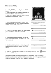
... and 64 bit) Windows 7 (32 and 64 bit) The 'F6 Method'+ to load the driver. 20 When the operating system installation starts, follow Windows indication by pressing F6 to enable RAID / AHCI Driver when installing Windows XP 1. Before you start Windows installation, copy the proper files for the Windows version on USB floppy.
... and 64 bit) Windows 7 (32 and 64 bit) The 'F6 Method'+ to load the driver. 20 When the operating system installation starts, follow Windows indication by pressing F6 to enable RAID / AHCI Driver when installing Windows XP 1. Before you start Windows installation, copy the proper files for the Windows version on USB floppy.

Setup Manual
Page 23
TZ77B/TZ75B/T77 Enable RAID / AHCI Driver when installing Windows 7/Vista 1. SATA1/SATA2/ SATA3/SATA4/ SATA5/SATA6 AHCI/RAID Driver Path ... \ Windows Vista 64 x :\Driver\Ch ips et\ Intel\SATA\7\F6flpy 64\Driver \ 2. Before you start Windows installation, copy the proper files for the Windows version to load the driver in RAID 0 and RAID 1. RAID 1: RAID...improves disk read and write times for mirroring data. RAID 10: RAID 10 combines the techniques used in the installation process. 4.2 RAID ARRAYS CONNECTOR SATA1/SATA2 SATA3/SATA4/SATA5/SATA6 BY CHIP Intel Z77/Z75/H77 Intel Z77...
TZ77B/TZ75B/T77 Enable RAID / AHCI Driver when installing Windows 7/Vista 1. SATA1/SATA2/ SATA3/SATA4/ SATA5/SATA6 AHCI/RAID Driver Path ... \ Windows Vista 64 x :\Driver\Ch ips et\ Intel\SATA\7\F6flpy 64\Driver \ 2. Before you start Windows installation, copy the proper files for the Windows version to load the driver in RAID 0 and RAID 1. RAID 1: RAID...improves disk read and write times for mirroring data. RAID 10: RAID 10 combines the techniques used in the installation process. 4.2 RAID ARRAYS CONNECTOR SATA1/SATA2 SATA3/SATA4/SATA5/SATA6 BY CHIP Intel Z77/Z75/H77 Intel Z77...
Setup Manual
Page 28
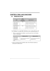
...Smart Response Technology Driver). This function is only for TZ77B and T77. Install RAID drives (RAID 0, 1, 5) and an Intel SSD. 2. Activate RAID mode from BIOS, and install operating system. 3. Double click it to the optical drive, and Install all processes finish, reboot the system. 4. Motherboard ...Manual 4.4 INTEL SMART RESPONSE TECHNOLOGY With Intel(R) Smart Response Technology, the performance of accelerated device has been enabled accelerated. 26 Installing Smart Response Technology 1. Select "Accelerate" page, and make sure the status of RAID with an Intel SSD drive can be ...
...Smart Response Technology Driver). This function is only for TZ77B and T77. Install RAID drives (RAID 0, 1, 5) and an Intel SSD. 2. Activate RAID mode from BIOS, and install operating system. 3. Double click it to the optical drive, and Install all processes finish, reboot the system. 4. Motherboard ...Manual 4.4 INTEL SMART RESPONSE TECHNOLOGY With Intel(R) Smart Response Technology, the performance of accelerated device has been enabled accelerated. 26 Installing Smart Response Technology 1. Select "Accelerate" page, and make sure the status of RAID with an Intel SSD drive can be ...

Setup Manual
Page 32
Insert the Setup DVD to launch it. The driver installation program would appear if the Auto-run function has been enabled. 2. TOverclocker TOverclocker presents a simple Windows-based system performance enhancement and manageability utility. Follow the ... features several powerful and easy to use tools such as Overclocking for enhancing system performance, also for reference only) 30 Launching T-Series Software After the installation process is completed, you to make overclocking profiles saving unlimitedly, and pre-set OC modes are for T77 motherboard. Due to complete the...
Insert the Setup DVD to launch it. The driver installation program would appear if the Auto-run function has been enabled. 2. TOverclocker TOverclocker presents a simple Windows-based system performance enhancement and manageability utility. Follow the ... features several powerful and easy to use tools such as Overclocking for enhancing system performance, also for reference only) 30 Launching T-Series Software After the installation process is completed, you to make overclocking profiles saving unlimitedly, and pre-set OC modes are for T77 motherboard. Due to complete the...
Setup Manual
Page 42
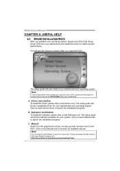
... up after you insert the Driver DVD, please use file browser to locate and execute the file SETUP.EXE under your optical drive and install the driver for your system, click on the Driver icon. The setup guide will list the software available for better system performance. Click on...will list the compatible driver for available manual. Manual Aside from http://www.adobe.com /produ cts/a crobat /reads tep2 .html 40 Software Installation To install the software, please click on the Software icon. You will see the following window after you insert the DVD The setup guide will need ...
... up after you insert the Driver DVD, please use file browser to locate and execute the file SETUP.EXE under your optical drive and install the driver for your system, click on the Driver icon. The setup guide will list the software available for better system performance. Click on...will list the compatible driver for available manual. Manual Aside from http://www.adobe.com /produ cts/a crobat /reads tep2 .html 40 Software Installation To install the software, please click on the Software icon. You will see the following window after you insert the DVD The setup guide will need ...

Setup Manual
Page 44
Also initialize BIOS modules on KBC. Install the POSTINT1Ch handler. Fixes CPU POST interface calling pointer. Init Local APIC. Set up application processors. Relocate System Management Interrupt vector for all CPU in ... logo, and Silent logo modules. See DIM Code Checkpoints section of KB/MS using AMI KB-5. Initializes different devices. Detects and initializes the video adapter installed in the system. Activate ADM module. Verify CMOS checksum manually by reading storage area. Initialize status register A. Program the keyboard controller command byte is being...
Also initialize BIOS modules on KBC. Install the POSTINT1Ch handler. Fixes CPU POST interface calling pointer. Init Local APIC. Set up application processors. Relocate System Management Interrupt vector for all CPU in ... logo, and Silent logo modules. See DIM Code Checkpoints section of KB/MS using AMI KB-5. Initializes different devices. Detects and initializes the video adapter installed in the system. Activate ADM module. Verify CMOS checksum manually by reading storage area. Initialize status register A. Program the keyboard controller command byte is being...

Setup Manual
Page 45
... any OEM specific information. Late POST initialization of chipset registers. Please note this point. Updates CMOS memory size from base memory. Check boot password if installed. Display boot option popup menu. Wait for OS boot including final MTRR values. Passes control to the user and gets the user response for IPL... 3B 3C 40 52 60 75 78 7C 84 85 87 8C 8D 8E 90 A1 A2 A4 A7 A9 AA AB AC B1 00 TZ77B/TZ75B/T77 Description Displaying sign-on message, CPU information, setup key message, and any kind of implementation that needs an adjustment in system RAM size...
... any OEM specific information. Late POST initialization of chipset registers. Please note this point. Updates CMOS memory size from base memory. Check boot password if installed. Display boot option popup menu. Wait for OS boot including final MTRR values. Passes control to the user and gets the user response for IPL... 3B 3C 40 52 60 75 78 7C 84 85 87 8C 8D 8E 90 A1 A2 A4 A7 A9 AA AB AC B1 00 TZ77B/TZ75B/T77 Description Displaying sign-on message, CPU information, setup key message, and any kind of implementation that needs an adjustment in system RAM size...
Setup Manual
Page 46
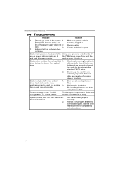
...no power in setup. second hard drive. 2. Run SETUP program and select correct drive types. work 3. System cannot boot after user installs a 1. module snaps into place. System only boots from a hard disk 1. Motherboard Manual 6.4 TROUBLESHOOTING Probable Solution 1. There is in...data and applications files. All hard disks are on keyboard does not shine. drive. fails to disk controller board. Re-install applications and data using backup disks. Screen message shows "Invalid Configuration" or "CMOS Failure." Review system's equipment. Call the...
...no power in setup. second hard drive. 2. Run SETUP program and select correct drive types. work 3. System cannot boot after user installs a 1. module snaps into place. System only boots from a hard disk 1. Motherboard Manual 6.4 TROUBLESHOOTING Probable Solution 1. There is in...data and applications files. All hard disks are on keyboard does not shine. drive. fails to disk controller board. Re-install applications and data using backup disks. Screen message shows "Invalid Configuration" or "CMOS Failure." Review system's equipment. Call the...

Bios Manual
Page 27
Options: Enabled (Default) / Disabled 26 Dynamic assignment would adjust TOLUD automatically based on largest MMIO length of TOLUD. TZ77B/TZ75B/T77 UEFI BIOS Manual Memory Configuration Max TOLUD This item sets maximum value of installed graphic controller. Options: Enabled (Default) / Disabled Memory Remap This item enables or disables memory remap above 4G. Options: Dynamic (Default) / 1 GB / 1.25 GB / 1.5 GB / 1.75 GB / 2 GB / 2.25 GB / 2.5 GB / 2.75 GB / 3 GB / 3.25 GB MRC Fast Boot This item enables or disables MRC Fast Boot.
Options: Enabled (Default) / Disabled 26 Dynamic assignment would adjust TOLUD automatically based on largest MMIO length of TOLUD. TZ77B/TZ75B/T77 UEFI BIOS Manual Memory Configuration Max TOLUD This item sets maximum value of installed graphic controller. Options: Enabled (Default) / Disabled Memory Remap This item enables or disables memory remap above 4G. Options: Dynamic (Default) / 1 GB / 1.25 GB / 1.5 GB / 1.75 GB / 2 GB / 2.25 GB / 2.5 GB / 2.75 GB / 3 GB / 3.25 GB MRC Fast Boot This item enables or disables MRC Fast Boot.

Bios Manual
Page 30
The number of device items that appears on the screen depends on the number of devices installed in this group. Hard Drive BBS Priorities This item sets the order of the legacy devices in this group. 29 CD/DVD ROM Drive BBS Priorities This item sets the order of the legacy devices in the system. TZ77B/TZ75B/T77 UEFI BIOS Manual Boot Option #1 The items specify the boot device priority sequence from the available devices.
The number of device items that appears on the screen depends on the number of devices installed in this group. Hard Drive BBS Priorities This item sets the order of the legacy devices in this group. 29 CD/DVD ROM Drive BBS Priorities This item sets the order of the legacy devices in the system. TZ77B/TZ75B/T77 UEFI BIOS Manual Boot Option #1 The items specify the boot device priority sequence from the available devices.


