Update Manual
Page 3
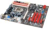
...lead to download the latest BIOS file for your BIOS via USB pen drive. 1. Go to the website to system boot failure. BIOSTAR BIOS flasher BIOSTAR BIOS Flasher is a BIOS flashing utility providing you an easy and simple way to update your reference only. Power on board may be...while booting up , press key to restart system. 8. Press the [Y] key to enter BIOS setup. All the information and content above are for the motherboard. 2. Updating BIOS with FAT32/16 format and single partition. 2. Select the proper BIOS file, and a message asking if you are subject to be ...
...lead to download the latest BIOS file for your BIOS via USB pen drive. 1. Go to the website to system boot failure. BIOSTAR BIOS flasher BIOSTAR BIOS Flasher is a BIOS flashing utility providing you an easy and simple way to update your reference only. Power on board may be...while booting up , press key to restart system. 8. Press the [Y] key to enter BIOS setup. All the information and content above are for the motherboard. 2. Updating BIOS with FAT32/16 format and single partition. 2. Select the proper BIOS file, and a message asking if you are subject to be ...

Setup Manual
Page 2
Table of Contents Chapter 1: Introduction 1 1.1 Before You Start 1 1.2 Package Checklist 1 1.3 Motherboard Features 2 1.4 Rear Panel Connectors 4 1.5 Motherboard Layout 5 Chapter 2: Hardware Installation 6 2.1 Installing Central Processing Unit (CPU 6 2.2 FAN Headers 8 2.3 Installing System Memory 9 2.4 Connectors and Slots 11 Chapter 3: Headers & Jumpers Setup 15 3.1 How to ...
Table of Contents Chapter 1: Introduction 1 1.1 Before You Start 1 1.2 Package Checklist 1 1.3 Motherboard Features 2 1.4 Rear Panel Connectors 4 1.5 Motherboard Layout 5 Chapter 2: Hardware Installation 6 2.1 Installing Central Processing Unit (CPU 6 2.2 FAN Headers 8 2.3 Installing System Memory 9 2.4 Connectors and Slots 11 Chapter 3: Headers & Jumpers Setup 15 3.1 How to ...

Setup Manual
Page 3
.... „ Avoid touching the components on the edge, do not try to area or your motherboard version. 1 CHAPTER 1: INTRODUCTION TZ77XE3/TZ75XE3 1.1 BEFORE YOU START Thank you take the motherboard out from dangerous area, such as heat source, humid air and water. „ The operating... temperatures of the board unless necessary. Before you start installing the motherboard, please make sure you follow the instructions below: „ Prepare a dry and stable working environment with sufficient lighting. „ Always disconnect...
.... „ Avoid touching the components on the edge, do not try to area or your motherboard version. 1 CHAPTER 1: INTRODUCTION TZ77XE3/TZ75XE3 1.1 BEFORE YOU START Thank you take the motherboard out from dangerous area, such as heat source, humid air and water. „ The operating... temperatures of the board unless necessary. Before you start installing the motherboard, please make sure you follow the instructions below: „ Prepare a dry and stable working environment with sufficient lighting. „ Always disconnect...

Setup Manual
Page 4
... / CFX) PCI Express Gen2 x 16 slot(x4) x1 Supports PCI-E Gen2 x16 expansion card PCI Express Gen2 x 1 slot x2 Supports PCI-E Gen2 x1 expansion cards 2 Motherboard Manual 1.3 MOTHERBOARD FEATURES SPEC Supports Execute Disable Bit / Enhanced Intel Socket 1155 SpeedStep® / Intel Architecture-64 / Extended CPU Intel Core i7 / i5 / i3 / Pentium / Celeron...
... / CFX) PCI Express Gen2 x 16 slot(x4) x1 Supports PCI-E Gen2 x16 expansion card PCI Express Gen2 x 1 slot x2 Supports PCI-E Gen2 x1 expansion cards 2 Motherboard Manual 1.3 MOTHERBOARD FEATURES SPEC Supports Execute Disable Bit / Enhanced Intel Socket 1155 SpeedStep® / Intel Architecture-64 / Extended CPU Intel Core i7 / i5 / i3 / Pentium / Celeron...

Setup Manual
Page 6
...In NOTE: USB3.0 ports (only supported by Windows 7) are backward compatible with HDMI 1.4a DVI: 1920 x 1200 @60Hz VGA: 2048 x 1536 @75Hz NOTE: This motherboard supports dual video output: Display Devices VGA DVI-D HDMI VGA DVI-D HDMI X A A A X S1, C, E A S1, C, E X z A = Single...= Clone Mode z E = Extended Desktop Mode z S1 = Single Pipe Single Display With One Display Device Disabled z X = Unsupported / Note Applicable 4 Motherboard Manual 1.4 REAR PANEL CONNECTORS PS /2 Ke yb oard VGA LA N USB2.0X2 HDMI DV I- NOTE: Maximum resolution: HDMI: 1920 x 1200 @60Hz, ...
...In NOTE: USB3.0 ports (only supported by Windows 7) are backward compatible with HDMI 1.4a DVI: 1920 x 1200 @60Hz VGA: 2048 x 1536 @75Hz NOTE: This motherboard supports dual video output: Display Devices VGA DVI-D HDMI VGA DVI-D HDMI X A A A X S1, C, E A S1, C, E X z A = Single...= Clone Mode z E = Extended Desktop Mode z S1 = Single Pipe Single Display With One Display Device Disabled z X = Unsupported / Note Applicable 4 Motherboard Manual 1.4 REAR PANEL CONNECTORS PS /2 Ke yb oard VGA LA N USB2.0X2 HDMI DV I- NOTE: Maximum resolution: HDMI: 1920 x 1200 @60Hz, ...
Setup Manual
Page 7
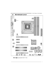
HDMI1 1.5 MOTHERBOARD LAYOUT USB_KBMS1 ATXPWR2 TZ77XE3/TZ75XE3 CPU_FAN1 DDR3_A1 DDR3_A2 DDR3_B1 DDR3_B2 VGA1 DVI1 USB3_0 RJ45USB1 Socket 1155 CP U 1 AUDIO1 SYS_FAN2 PEX16_1 ATXPWR1 LAN PEX1_1 F_ AUDIO1 CODEC PEX1_2 PEX16_2 PCI1 PCI2 PEX16_3 SYS_FAN1 JSPDIFOUT1 CIR1 J _C OM1 Intel Z77/ Z75 BIOS JCMOS 1 Super I/O BAT1 J FR ON T_U SB3_1 F_USB1 SATA6 SATA5 SW_RST1 SATA4 SATA3 SATA2 SATA1 F_USB2 SW_PW R1 PANEL1 Note: ■ represents the 1st pin. 5
HDMI1 1.5 MOTHERBOARD LAYOUT USB_KBMS1 ATXPWR2 TZ77XE3/TZ75XE3 CPU_FAN1 DDR3_A1 DDR3_A2 DDR3_B1 DDR3_B2 VGA1 DVI1 USB3_0 RJ45USB1 Socket 1155 CP U 1 AUDIO1 SYS_FAN2 PEX16_1 ATXPWR1 LAN PEX1_1 F_ AUDIO1 CODEC PEX1_2 PEX16_2 PCI1 PCI2 PEX16_3 SYS_FAN1 JSPDIFOUT1 CIR1 J _C OM1 Intel Z77/ Z75 BIOS JCMOS 1 Super I/O BAT1 J FR ON T_U SB3_1 F_USB1 SATA6 SATA5 SW_RST1 SATA4 SATA3 SATA2 SATA1 F_USB2 SW_PW R1 PANEL1 Note: ■ represents the 1st pin. 5

Setup Manual
Page 8
When the CPU is removed, cover the Pin Cap on the empty socket to remove the pin cap. Please refer below instruction to ensure pin legs won't be damaged. 2. Motherboard Manual CHAPTER 2: HARDWARE INSTALLATION 2.1 INSTALLING CENTRAL PROCESSING UNIT (CPU) Notice: 1. The motherboard might equip with two different types of pin cap. Step 1: Pull the socket locking lever out from the socket and then raise the lever up. Step 2: Remove the Pin Cap. 6 Remove Pin Cap before installation, and make good preservation for future use.
When the CPU is removed, cover the Pin Cap on the empty socket to remove the pin cap. Please refer below instruction to ensure pin legs won't be damaged. 2. Motherboard Manual CHAPTER 2: HARDWARE INSTALLATION 2.1 INSTALLING CENTRAL PROCESSING UNIT (CPU) Notice: 1. The motherboard might equip with two different types of pin cap. Step 1: Pull the socket locking lever out from the socket and then raise the lever up. Step 2: Remove the Pin Cap. 6 Remove Pin Cap before installation, and make good preservation for future use.

Setup Manual
Page 10
... Control SYS_FAN1/SYS_FAN2: System Fan Headers S Y S_FAN2 3 Pin 1 1 2 3 Assignment Ground +12V FAN RPM rate sense 13 S Y S_FAN1 Note: The SYS_FAN1/SYS_FAN2 support 3-pin head connectors; Motherboard Manual 2.2 FAN HEADERS These fan headers support cooling-fans built in the computer.
... Control SYS_FAN1/SYS_FAN2: System Fan Headers S Y S_FAN2 3 Pin 1 1 2 3 Assignment Ground +12V FAN RPM rate sense 13 S Y S_FAN1 Note: The SYS_FAN1/SYS_FAN2 support 3-pin head connectors; Motherboard Manual 2.2 FAN HEADERS These fan headers support cooling-fans built in the computer.

Setup Manual
Page 12
Motherboard Manual B. Dual Channel Memory Installation Please refer to the following requirements to activate Dual Channel function: Install memory module of the memory module must be ...
Motherboard Manual B. Dual Channel Memory Installation Please refer to the following requirements to activate Dual Channel function: Install memory module of the memory module must be ...

Setup Manual
Page 13
2.4 CONNECTORS AND SLOTS TZ77XE3/TZ75XE3 SATA1/SATA2: Serial ATA3.0 Connectors The motherboard has a PCI to SATA Controller with 4 channels SATA2 interface, it satisfies the SATA 3.0 spec and with transfer rate of 6.0Gb/s. S ATA 2 S ATA 1 7 41 Pin Assignment 1 Ground 2 TX+ 3 TX4 Ground 5 RX6 RX+ 7 Ground SATA3 ~ 6: Serial ATA2.0 Connectors The motherboard has a PCI to SATA Controller with 2 channels SATA interface, it satisfies the SATA 2.0 spec and with transfer rate of 3.0Gb/s. SATA6 SATA4 SATA5 SATA3 7 41 Pin Assignment 1 Ground 2 TX+ 3 TX4 Ground 5 RX6 RX+ 7 Ground 11
2.4 CONNECTORS AND SLOTS TZ77XE3/TZ75XE3 SATA1/SATA2: Serial ATA3.0 Connectors The motherboard has a PCI to SATA Controller with 4 channels SATA2 interface, it satisfies the SATA 3.0 spec and with transfer rate of 6.0Gb/s. S ATA 2 S ATA 1 7 41 Pin Assignment 1 Ground 2 TX+ 3 TX4 Ground 5 RX6 RX+ 7 Ground SATA3 ~ 6: Serial ATA2.0 Connectors The motherboard has a PCI to SATA Controller with 2 channels SATA interface, it satisfies the SATA 2.0 spec and with transfer rate of 3.0Gb/s. SATA6 SATA4 SATA5 SATA3 7 41 Pin Assignment 1 Ground 2 TX+ 3 TX4 Ground 5 RX6 RX+ 7 Ground 11

Setup Manual
Page 14
... x8 when SLI / CFX is enabled; Data transfer bandwidth up to 500MB/s per direction, for an aggregate of 16GB/s simultaneously per direction; 1GB/s in total. Motherboard Manual PEX16_1/ PEX16_2: PCI-Express Gen3 x16 (x16 / x8) (Nvidia SLI and AMD CrossFireX) Slots - PCI-E 3.0 is x8. - PCI-Express 2.0 compliant. - PEX16_1 PEX1_1 PEX1_2 PEX16_2...
... x8 when SLI / CFX is enabled; Data transfer bandwidth up to 500MB/s per direction, for an aggregate of 16GB/s simultaneously per direction; 1GB/s in total. Motherboard Manual PEX16_1/ PEX16_2: PCI-Express Gen3 x16 (x16 / x8) (Nvidia SLI and AMD CrossFireX) Slots - PCI-E 3.0 is x8. - PCI-Express 2.0 compliant. - PEX16_1 PEX1_1 PEX1_2 PEX16_2...

Setup Manual
Page 15
If the CPU power plug is designated as 32 bits. This PCI slot is 4-pin, please plug it is equipped with 2 standard PCI slots. PCI 1 PCI2 ATXPWR2: ATX Power Source Connectors These connectors provide +12V to CPU power circuit. TZ77XE3/TZ75XE3 PCI1/PCI2: Peripheral Component Interconnect Slots This motherboard is a bus standard for expansion cards. PCI stands for Peripheral Component Interconnect, and it into Pin 1-2-5-6 of ATXPWR2. 8 4 Pin Assignment 1 +12V 2 +12V 5 13 +12V 4 +12V 5 Ground 6 Ground 7 Ground 8 Ground 13
If the CPU power plug is designated as 32 bits. This PCI slot is 4-pin, please plug it is equipped with 2 standard PCI slots. PCI 1 PCI2 ATXPWR2: ATX Power Source Connectors These connectors provide +12V to CPU power circuit. TZ77XE3/TZ75XE3 PCI1/PCI2: Peripheral Component Interconnect Slots This motherboard is a bus standard for expansion cards. PCI stands for Peripheral Component Interconnect, and it into Pin 1-2-5-6 of ATXPWR2. 8 4 Pin Assignment 1 +12V 2 +12V 5 13 +12V 4 +12V 5 Ground 6 Ground 7 Ground 8 Ground 13

Setup Manual
Page 16
Motherboard Manual ATXPWR1: ATX Power Source Connector This connector allows user to connect 24-pin power connector on the ATX power supply. 12 24 1 13 Pin Assignment Pin Assignment 13 +3.3V 14 -12V 15 Ground 16 PS_ON 17 Ground 18 Ground 19 Ground 20 NC 21 +5V 22 +5V 23 +5V 24 Ground 1 +3.3V 2 +3.3V 3 Ground 4 +5V 5 Ground 6 +5V 7 Ground 8 PW_OK 9 Standby Voltage+5V 10 +12V 11 +12V 12 +3.3V Note: Before you power on the system, please make sure that ATXPWR1 and ATXPWR2 connectors have been well plugged-in. 14
Motherboard Manual ATXPWR1: ATX Power Source Connector This connector allows user to connect 24-pin power connector on the ATX power supply. 12 24 1 13 Pin Assignment Pin Assignment 13 +3.3V 14 -12V 15 Ground 16 PS_ON 17 Ground 18 Ground 19 Ground 20 NC 21 +5V 22 +5V 23 +5V 24 Ground 1 +3.3V 2 +3.3V 3 Ground 4 +5V 5 Ground 6 +5V 7 Ground 8 PW_OK 9 Standby Voltage+5V 10 +12V 11 +12V 12 +3.3V Note: Before you power on the system, please make sure that ATXPWR1 and ATXPWR2 connectors have been well plugged-in. 14

Setup Manual
Page 18
... D2- 13 Ground 14 SSTX2+ 15 SSTX2- 16 Ground 17 SSRX2+ 18 SSRX2- 19 VBUS1 20 Key NOTE: USB3.0 is only supported by Windows 7. 16 Motherboard Manual F_USB1/F_USB2: Headers for USB 3.0 Ports at Front Panel These headers allow user to connect additional USB cable on the PC front panel, and...
... D2- 13 Ground 14 SSTX2+ 15 SSTX2- 16 Ground 17 SSRX2+ 18 SSRX2- 19 VBUS1 20 Key NOTE: USB3.0 is only supported by Windows 7. 16 Motherboard Manual F_USB1/F_USB2: Headers for USB 3.0 Ports at Front Panel These headers allow user to connect additional USB cable on the PC front panel, and...

Setup Manual
Page 20
Motherboard Manual JCMOS1: Clear CMOS Header Placing the jumper on the AC. 6. Set the jumper to "Pin 2-3 close ". 5. Please carefully follow the procedures to send 9 Ring .... 2 10 1 9 Pin Assignment 1 Carrier detect 2 Received data 3 Transmitted data 4 Data terminal ready 5 Signal ground 6 Data set ready 7 Request to send 8 Clear to avoid damaging the motherboard. 13 Pin 1-2 Close: Normal Operation (default). 13 13 Pin 2-3 Close: Clear CMOS data. ※ Clear CMOS Procedures: 1. J_COM1: Serial Port Connector The...
Motherboard Manual JCMOS1: Clear CMOS Header Placing the jumper on the AC. 6. Set the jumper to "Pin 2-3 close ". 5. Please carefully follow the procedures to send 9 Ring .... 2 10 1 9 Pin Assignment 1 Carrier detect 2 Received data 3 Transmitted data 4 Data terminal ready 5 Signal ground 6 Data set ready 7 Request to send 8 Clear to avoid damaging the motherboard. 13 Pin 1-2 Close: Normal Operation (default). 13 13 Pin 2-3 Close: Clear CMOS data. ※ Clear CMOS Procedures: 1. J_COM1: Serial Port Connector The...
Setup Manual
Page 22
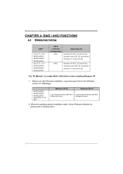
... version on USB floppy. When the operating system installation starts, follow Windows indication by pressing F6 to enable RAID / AHCI Driver when installing Windows XP 1. Motherboard Manual CHAPTER 4: RAID / AHCI FUNCTIONS 4.1 OPERATING SYSTEM CHIP Intel Z77 / Z75 SATA1/SATA2/ SATA3/SATA4/ SATA5/SATA6 Intel Z77 / Z75 SATA1/SATA2/ SATA3/SATA4/ SATA5...
... version on USB floppy. When the operating system installation starts, follow Windows indication by pressing F6 to enable RAID / AHCI Driver when installing Windows XP 1. Motherboard Manual CHAPTER 4: RAID / AHCI FUNCTIONS 4.1 OPERATING SYSTEM CHIP Intel Z77 / Z75 SATA1/SATA2/ SATA3/SATA4/ SATA5/SATA6 Intel Z77 / Z75 SATA1/SATA2/ SATA3/SATA4/ SATA5...

Setup Manual
Page 24
Motherboard Manual 4.3 HOW RAID WORKS RAID 0: The controller "stripes" data across multiple drives in a RAID 0 array system. It breaks up to 6 or 8. The size of each ...
Motherboard Manual 4.3 HOW RAID WORKS RAID 0: The controller "stripes" data across multiple drives in a RAID 0 array system. It breaks up to 6 or 8. The size of each ...

Setup Manual
Page 26
... on the platform. Benefits: Optimizes for both fault tolerance and performance, allowing for data redundancy, the same as RAID level 1. Fault Tolerance: Yes. Motherboard Manual RAID 10: RAID 1 drives can be simultaneously used with other RAID levels in a RAID 10 solution for improved resiliency, performance and rebuild performance. Resulting...
... on the platform. Benefits: Optimizes for both fault tolerance and performance, allowing for data redundancy, the same as RAID level 1. Fault Tolerance: Yes. Motherboard Manual RAID 10: RAID 1 drives can be simultaneously used with other RAID levels in a RAID 10 solution for improved resiliency, performance and rebuild performance. Resulting...

Setup Manual
Page 28
... from BIOS, and install operating system. 3. Select "Accelerate" page, and make sure the status of RAID with an Intel SSD drive can be improved better. Motherboard Manual 4.4 INTEL SMART RESPONSE TECHNOLOGY With Intel(R) Smart Response Technology, the performance of accelerated device has been enabled accelerated. 26 Install RAID drives (RAID 0, 1, 5) and...
... from BIOS, and install operating system. 3. Select "Accelerate" page, and make sure the status of RAID with an Intel SSD drive can be improved better. Motherboard Manual 4.4 INTEL SMART RESPONSE TECHNOLOGY With Intel(R) Smart Response Technology, the performance of accelerated device has been enabled accelerated. 26 Install RAID drives (RAID 0, 1, 5) and...

Setup Manual
Page 30
Motherboard Manual NOTE Overclock is not recommended for any overclocking performance. We also would not guarantee any hardware damage which may be caused by CPU/System ...
Motherboard Manual NOTE Overclock is not recommended for any overclocking performance. We also would not guarantee any hardware damage which may be caused by CPU/System ...

