Setup Manual
Page 2
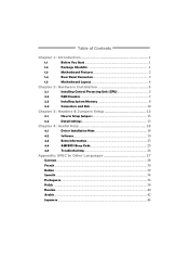
Table of Contents Chapter 1: Introduction 1 1.1 Before You Start 1 1.2 Package Checklist 1 1.3 Motherboard Features 2 1.4 Rear Panel Connectors 3 1.5 Motherboard Layout 4 Chapter 2: Hardware Installation 5 2.1 Installing Central Processing Unit (CPU 5 2.2 FAN Headers 7 2.3 Installing System Memory 8 2.4 Connectors and Slots 10 Chapter 3: Headers & Jumpers Setup 13 3.1 How to ...
Table of Contents Chapter 1: Introduction 1 1.1 Before You Start 1 1.2 Package Checklist 1 1.3 Motherboard Features 2 1.4 Rear Panel Connectors 3 1.5 Motherboard Layout 4 Chapter 2: Hardware Installation 5 2.1 Installing Central Processing Unit (CPU 5 2.2 FAN Headers 7 2.3 Installing System Memory 8 2.4 Connectors and Slots 10 Chapter 3: Headers & Jumpers Setup 13 3.1 How to ...

Setup Manual
Page 3
... due to bend or flex the board. „ Do not leave any unfastened small parts inside the case after installation. Hold the board on motherboard or the rear side of the computer should be 0 to 45 degrees Celsius. 1.2 PACKAGE CHECKLIST Serial ATA Cable X 2 Rear I/O Panel for...and water. „ The operating temperatures of the board unless necessary. CHAPTER 1: INTRODUCTION H55 HD 1.1 BEFORE YOU START Thank you take the motherboard out from anti-static bag, ground yourself properly by touching any safely grounded appliance, or use grounded wrist strap to remove the static charge. ...
... due to bend or flex the board. „ Do not leave any unfastened small parts inside the case after installation. Hold the board on motherboard or the rear side of the computer should be 0 to 45 degrees Celsius. 1.2 PACKAGE CHECKLIST Serial ATA Cable X 2 Rear I/O Panel for...and water. „ The operating temperatures of the board unless necessary. CHAPTER 1: INTRODUCTION H55 HD 1.1 BEFORE YOU START Thank you take the motherboard out from anti-static bag, ground yourself properly by touching any safely grounded appliance, or use grounded wrist strap to remove the static charge. ...
Setup Manual
Page 4
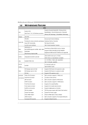
Motherboard Manual 1.3 MOTHERBOARD FEATURES SPEC Supports Execute Disable Bit / Enhanced Intel Socket 1156 CPU SpeedStep® / Intel Architecture-64 / Extended Intel Core i7 / i5 / i3/ Pentium processor Memory ...
Motherboard Manual 1.3 MOTHERBOARD FEATURES SPEC Supports Execute Disable Bit / Enhanced Intel Socket 1156 CPU SpeedStep® / Intel Architecture-64 / Extended Intel Core i7 / i5 / i3/ Pentium processor Memory ...

Setup Manual
Page 5
NOTE: Maximum resolution: HDMI: 1920 x 1200 @60Hz DVI: 1920 x 1200 @60Hz VGA: 2048 x 1536 @75Hz NOTE: This motherboard supports Multiple VGA output, and the configuration is as below: (HDMI is not supported under DOS and BIOS setup.) Display Devices Enabled VGA + HDMI VGA + ... x1 Connect to DVI monitor x1 Connect to RJ-45 ethernet cable x4 Connect to USB devices x3 Provide Audio-In/Out and microphone connection Biostar reserves the right to add or remove support for any OS with or without notice 1.4 REAR PANEL CONNECTORS PS/2 Keyboard / Mouse LAN USBX2 HDMI DVI...
NOTE: Maximum resolution: HDMI: 1920 x 1200 @60Hz DVI: 1920 x 1200 @60Hz VGA: 2048 x 1536 @75Hz NOTE: This motherboard supports Multiple VGA output, and the configuration is as below: (HDMI is not supported under DOS and BIOS setup.) Display Devices Enabled VGA + HDMI VGA + ... x1 Connect to DVI monitor x1 Connect to RJ-45 ethernet cable x4 Connect to USB devices x3 Provide Audio-In/Out and microphone connection Biostar reserves the right to add or remove support for any OS with or without notice 1.4 REAR PANEL CONNECTORS PS/2 Keyboard / Mouse LAN USBX2 HDMI DVI...

Setup Manual
Page 6
Motherboard Manual 1.5 MOTHERBOARD LAYOUT U S BK B 1 DD R 3_B 1 DD R 3_A 1 HDMI1 D V I1 Socket 1156 C PU 1 ID E 1 C P U_FA N1 ATX PW R 1 VGA1 SATA3 SATA1 SATA4 SATA2 JU S BV 1 R J 45U S B1 A U DI O1 ATX P WR 2 PEX16_1 BAT1 BIOS LAN PCI1 CODEC PCI2 J S P DI FOU T1 PEX1_1 Super I/O F_AUDIO1 J_PRINT1 J_COM1 H55 J U SB V 2 JCMOS1 SY S _FA N 1 CIR1 F_USB2 F_USB1 PANEL1 Note: ■ represents the 1st pin. 4
Motherboard Manual 1.5 MOTHERBOARD LAYOUT U S BK B 1 DD R 3_B 1 DD R 3_A 1 HDMI1 D V I1 Socket 1156 C PU 1 ID E 1 C P U_FA N1 ATX PW R 1 VGA1 SATA3 SATA1 SATA4 SATA2 JU S BV 1 R J 45U S B1 A U DI O1 ATX P WR 2 PEX16_1 BAT1 BIOS LAN PCI1 CODEC PCI2 J S P DI FOU T1 PEX1_1 Super I/O F_AUDIO1 J_PRINT1 J_COM1 H55 J U SB V 2 JCMOS1 SY S _FA N 1 CIR1 F_USB2 F_USB1 PANEL1 Note: ■ represents the 1st pin. 4
Setup Manual
Page 8
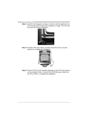
The CPU will fit only in the correct orientation. Step 4: Hold the CPU down firmly, and then lower the lever to locked position to complete the installation. 6 Step 5: Put the CPU Fan and heatsink assembly on the CPU and buckle it on CPU should point forwards this triangular cut edge on socket, and the golden dot on the retention frame. Connect the CPU FAN power cable into the CPU_FAN1 to complete the installation. Motherboard Manual Step 3: Look for the triangular cut edge.
The CPU will fit only in the correct orientation. Step 4: Hold the CPU down firmly, and then lower the lever to locked position to complete the installation. 6 Step 5: Put the CPU Fan and heatsink assembly on the CPU and buckle it on CPU should point forwards this triangular cut edge on socket, and the golden dot on the retention frame. Connect the CPU FAN power cable into the CPU_FAN1 to complete the installation. Motherboard Manual Step 3: Look for the triangular cut edge.

Setup Manual
Page 10
Unlock a DIMM slot by pressing the retaining clips outward. Align a DIMM on the slot such that the notch on the DIMM matches the break on the Slot. 2. Insert the DIMM vertically and firmly into the slot until the retaining chip snap back in place and the DIMM is properly seated. 8 Motherboard Manual 2.3 INSTALLING SYSTEM MEMORY A. DDR3 module DDR 3_B1 DDR 3_A1 1.
Unlock a DIMM slot by pressing the retaining clips outward. Align a DIMM on the slot such that the notch on the DIMM matches the break on the Slot. 2. Insert the DIMM vertically and firmly into the slot until the retaining chip snap back in place and the DIMM is properly seated. 8 Motherboard Manual 2.3 INSTALLING SYSTEM MEMORY A. DDR3 module DDR 3_B1 DDR 3_A1 1.
Setup Manual
Page 12
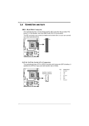
... AND SLOTS IDE1: Hard Disk Connector The motherboard has a 32-bit Enhanced PCI IDE Controller that provides PIO Mode 0~4, Bus Master, and Ultra DMA 33/66/100/133 functionality. SATA3 SATA1 SATA4 SATA2 7 4 1 ... connector can connect a master and a slave drive, so you can connect up to two hard disk drives. 40 39 2 1 SATA1~SATA4: Serial ATA Connectors The motherboard has a PCI to SATA Controller with 4channels SATA interface, it satisfies the SATA 2.0 spec and with transfer rate of 3Gb/s.
... AND SLOTS IDE1: Hard Disk Connector The motherboard has a 32-bit Enhanced PCI IDE Controller that provides PIO Mode 0~4, Bus Master, and Ultra DMA 33/66/100/133 functionality. SATA3 SATA1 SATA4 SATA2 7 4 1 ... connector can connect a master and a slave drive, so you can connect up to two hard disk drives. 40 39 2 1 SATA1~SATA4: Serial ATA Connectors The motherboard has a PCI to SATA Controller with 4channels SATA interface, it satisfies the SATA 2.0 spec and with transfer rate of 3Gb/s.
Setup Manual
Page 14
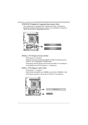
...: PCI-Express Gen2 x16 Slot - This PCI slot is equipped with 2 standard PCI slots. Data transfer bandwidth up to 250MB/s per direction, for expansion cards. Motherboard Manual PCI1/PCI2: Peripheral Component Interconnect Slots This...
...: PCI-Express Gen2 x16 Slot - This PCI slot is equipped with 2 standard PCI slots. Data transfer bandwidth up to 250MB/s per direction, for expansion cards. Motherboard Manual PCI1/PCI2: Peripheral Component Interconnect Slots This...

Setup Manual
Page 16
... USB ports at F_USB1/F_USB2. JUSBV2: +5V STB for USB ports at USBKB1/RJ45USB1. JUSBV2: +5V for USB ports at Front Panel This motherboard provides 2 USB 2.0 headers, which allows user to connect additional USB cable on the PC front panel, and also can be connected with internal ...USB devices, like USB card reader. JUSBV1 3 1 13 JUSBV2 13 Pin 1-2 close 13 Pin 2-3 close 14 Motherboard Manual F_USB1/F_USB2: Headers for USB 2.0 Ports at F_USB1/F_USB2. F_USB2 F_ USB1 2 10 1 9 Pin Assignment 1 +5V (fused) 2 +5V (fused) 3 USB4 USB5 USB+ 6 ...
... USB ports at F_USB1/F_USB2. JUSBV2: +5V STB for USB ports at USBKB1/RJ45USB1. JUSBV2: +5V for USB ports at Front Panel This motherboard provides 2 USB 2.0 headers, which allows user to connect additional USB cable on the PC front panel, and also can be connected with internal ...USB devices, like USB card reader. JUSBV1 3 1 13 JUSBV2 13 Pin 1-2 close 13 Pin 2-3 close 14 Motherboard Manual F_USB1/F_USB2: Headers for USB 2.0 Ports at F_USB1/F_USB2. F_USB2 F_ USB1 2 10 1 9 Pin Assignment 1 +5V (fused) 2 +5V (fused) 3 USB4 USB5 USB+ 6 ...

Setup Manual
Page 18
...17 Data 7 18 Ground 19 -ACK 20 Ground 21 Busy 22 Ground 23 PE 24 Ground 25 SCLT 26 Key J_COM1: Serial port Connector The motherboard has a Serial Port Connector for connecting RS-232 Port. Pin Assignment 1 Carrier detect 2 Received data 3 Transmitted data 4 Data terminal ready 5 Signal... ground 6 Data set ready 7 Request to send 2 10 8 Clear to connector printer on the PC. Motherboard Manual J_PRINT1: Printer Port Connector This header allows you to send 9 Ring indicator 10 NC 1 9 16
...17 Data 7 18 Ground 19 -ACK 20 Ground 21 Busy 22 Ground 23 PE 24 Ground 25 SCLT 26 Key J_COM1: Serial port Connector The motherboard has a Serial Port Connector for connecting RS-232 Port. Pin Assignment 1 Carrier detect 2 Received data 3 Transmitted data 4 Data terminal ready 5 Signal... ground 6 Data set ready 7 Request to send 2 10 8 Clear to connector printer on the PC. Motherboard Manual J_PRINT1: Printer Port Connector This header allows you to send 9 Ring indicator 10 NC 1 9 16

Setup Manual
Page 19
.... CIR1: Consumer IR Connector This header is for five seconds. 4. Power on pin2-3 allows user to "Pin 1-2 close ". 3. Set the jumper to avoid damaging the motherboard. 3 1 Pin 1-2 Close: Normal Operation (Default). 3 1 3 1 Pin 2-3 Close: Clear CMOS data. ※ Clear CMOS Procedures: 1. Please carefully follow the procedures to "Pin 2-3 close...
.... CIR1: Consumer IR Connector This header is for five seconds. 4. Power on pin2-3 allows user to "Pin 1-2 close ". 3. Set the jumper to avoid damaging the motherboard. 3 1 Pin 1-2 Close: Normal Operation (Default). 3 1 3 1 Pin 2-3 Close: Clear CMOS data. ※ Clear CMOS Procedures: 1. Please carefully follow the procedures to "Pin 2-3 close...
Setup Manual
Page 20
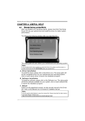
...please use file browser to open the manual file. The setup guide will auto detect your optical drive and install the driver for your motherboard and operating system. The setup guide will need Acrobat Reader to locate and execute the file SETUP.EXE under your optical drive. Click ... paperback manual, we also provide manual in the Driver CD. Note: You will list the software available for better system performance. Motherboard Manual CHAPTER 4: USEFUL HELP 4.1 DRIVER INSTALLATION NOTE After you installed your operating system, please insert the Fully Setup Driver CD into your...
...please use file browser to open the manual file. The setup guide will auto detect your optical drive and install the driver for your motherboard and operating system. The setup guide will need Acrobat Reader to locate and execute the file SETUP.EXE under your optical drive. Click ... paperback manual, we also provide manual in the Driver CD. Note: You will list the software available for better system performance. Motherboard Manual CHAPTER 4: USEFUL HELP 4.1 DRIVER INSTALLATION NOTE After you installed your operating system, please insert the Fully Setup Driver CD into your...
Setup Manual
Page 22
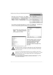
... appears asking you are not using eHot-Line service. click "Send" to confirm or "Do Not Send" to the following web http://www.biostar.com.tw/app/en-us/about/contact.php for your default e-mail client application, you want to save the system information to a .txt ...to our tech support with any other third parties, so please feel free to provide your system information while using Outlook Express as your confirmation; Motherboard Manual After filling up this information to a .txt file, click "Save As..." A warning dialog would appear asking for getting our contact information...
... appears asking you are not using eHot-Line service. click "Send" to confirm or "Do Not Send" to the following web http://www.biostar.com.tw/app/en-us/about/contact.php for your default e-mail client application, you want to save the system information to a .txt ...to our tech support with any other third parties, so please feel free to provide your system information while using Outlook Express as your confirmation; Motherboard Manual After filling up this information to a .txt file, click "Save As..." A warning dialog would appear asking for getting our contact information...

Setup Manual
Page 23
H55 HD BIOS Update BIOS Update is a convenient utility which allows you to save file and enter file name. (We recommend that the file name should be English/number and no longer than 7 characters.) Then click Save. 21 Choose the position to update your motherboard BIOS under Windows system. AWARD BIOS Show current BIOS information AMI BIOS Clear CMOS function (Only for AWARD BIOS) Save current BIOS to a .bin file Update BIOS with a BIOS file Once click on this button, the saving dialog will show.
H55 HD BIOS Update BIOS Update is a convenient utility which allows you to save file and enter file name. (We recommend that the file name should be English/number and no longer than 7 characters.) Then click Save. 21 Choose the position to update your motherboard BIOS under Windows system. AWARD BIOS Show current BIOS information AMI BIOS Clear CMOS function (Only for AWARD BIOS) Save current BIOS to a .bin file Update BIOS with a BIOS file Once click on this button, the saving dialog will show.
Setup Manual
Page 24
... run with the proper BIOS file, and this manual. 22 Please do not open dialog will show for updating, then click on Clear CMOS first. Motherboard Manual Before doing this process.
... run with the proper BIOS file, and this manual. 22 Please do not open dialog will show for updating, then click on Clear CMOS first. Motherboard Manual Before doing this process.

Setup Manual
Page 25
...: 1. Clear the CMOS data. (See "Close CMOS Header: JCMOS1" section) 2. When the CPU is rotated normally. 3. Wait for seconds. 3. CPU fan is over heated, the motherboard will shutdown automatically to relief the CPU protection function. 1. CPU fan speed is placed evenly with the CPU speed. Power on system for seconds. 2. The...
...: 1. Clear the CMOS data. (See "Close CMOS Header: JCMOS1" section) 2. When the CPU is rotated normally. 3. Wait for seconds. 3. CPU fan is over heated, the motherboard will shutdown automatically to relief the CPU protection function. 1. CPU fan speed is placed evenly with the CPU speed. Power on system for seconds. 2. The...
Setup Manual
Page 26
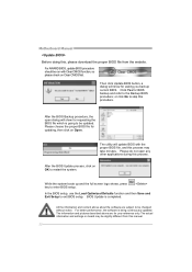
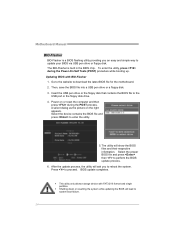
... the POST process. Insert the USB pen drive or the floppy disk that contains the BIOS file to download the latest BIOS file for the motherboard. 2. A select dialog as the picture on or reset the computer and then press during the Power-On Self Tests (POST) procedure while booting... BIOS file into a USB pen drive or a floppy disk. 3. Select the proper BIOS file and press then to perform the BIOS update process. 6. Motherboard Manual BIO-Flasher BIO-Flasher is built in the BIOS chip. The BIO-Flasher is a BIOS flashing utility providing you to reboot the system. z Shutting...
... the POST process. Insert the USB pen drive or the floppy disk that contains the BIOS file to download the latest BIOS file for the motherboard. 2. A select dialog as the picture on or reset the computer and then press during the Power-On Self Tests (POST) procedure while booting... BIOS file into a USB pen drive or a floppy disk. 3. Select the proper BIOS file and press then to perform the BIOS update process. 6. Motherboard Manual BIO-Flasher BIO-Flasher is built in the BIOS chip. The BIO-Flasher is a BIOS flashing utility providing you to reboot the system. z Shutting...

Setup Manual
Page 27
... beep codes are not generated when all other expansion cards are absent, consult your system manufacturer. This will reveal the malfunctioning card. Before declaring the motherboard beyond all expansion cards except the video adapter. Consult your system manufacturer's technical support. Insert the cards back into the system one of Beeps Troubleshooting...
... beep codes are not generated when all other expansion cards are absent, consult your system manufacturer. This will reveal the malfunctioning card. Before declaring the motherboard beyond all expansion cards except the video adapter. Consult your system manufacturer's technical support. Insert the cards back into the system one of Beeps Troubleshooting...
Setup Manual
Page 28
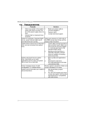
Motherboard Manual 4.5 TROUBLESHOOTING Probable Solution 1. drive, but system 2. check the drive type in . Reformat the hard drive. second hard drive. 2. Set master/slave jumpers correctly. Replace ...
Motherboard Manual 4.5 TROUBLESHOOTING Probable Solution 1. drive, but system 2. check the drive type in . Reformat the hard drive. second hard drive. 2. Set master/slave jumpers correctly. Replace ...

