Setup Manual
Page 1
...and product names are designed to the contents here without first obtaining the vendor's approval in writing. These limits are trademarks of this user's manual is no representations or warranties with the instructions, may cause harmful interference to be changed without notice and we will not occur in a ... communications. The vendor makes no guarantee that interference will not be responsible for any party beforehand. The content of their respective companies. TA770 A2+ Setup Manual FCC Information and Copyright This equipment has been tested and found in this user...
...and product names are designed to the contents here without first obtaining the vendor's approval in writing. These limits are trademarks of this user's manual is no representations or warranties with the instructions, may cause harmful interference to be changed without notice and we will not occur in a ... communications. The vendor makes no guarantee that interference will not be responsible for any party beforehand. The content of their respective companies. TA770 A2+ Setup Manual FCC Information and Copyright This equipment has been tested and found in this user...
Setup Manual
Page 3
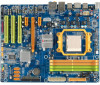
...remove the static charge. „ Avoid touching the components on motherboard or the rear side of the board unless necessary. CHAPTER 1: INTRODUCTION TA770 A2+ 1.1 BEFORE YOU START Thank you take the motherboard out from dangerous area, such as heat source, humid air and water. 1.2 ...dry and stable working environment with sufficient lighting. „ Always disconnect the computer from power outlet before operation. „ Before you for ATX Case X 1 User's Manual X 1 Fully Setup Driver CD X 1 FDD Cable X 1 (optional) USB 2.0 Cable X1 (optional) S/PDIF out Cable X 1 (optional) Note: The ...
...remove the static charge. „ Avoid touching the components on motherboard or the rear side of the board unless necessary. CHAPTER 1: INTRODUCTION TA770 A2+ 1.1 BEFORE YOU START Thank you take the motherboard out from dangerous area, such as heat source, humid air and water. 1.2 ...dry and stable working environment with sufficient lighting. „ Always disconnect the computer from power outlet before operation. „ Before you for ATX Case X 1 User's Manual X 1 Fully Setup Driver CD X 1 FDD Cable X 1 (optional) USB 2.0 Cable X1 (optional) S/PDIF out Cable X 1 (optional) Note: The ...
Setup Manual
Page 4
... 8718F Provides the most commonly used legacy Super Provides the most commonly used legacy Super I/O functionality. SATA Version 2.0 specification compliant. SATA Version 2.0 specification compliant. Motherboard Manual 1.3 MOTHERBOARD FEATURES Ver 5.x Ver 6.x Socket AM2 / AM2+ Socket AM2 / AM2+ AMD Athlon 64 / Athlon 64 FX / Athlon 64 X2 / AMD Athlon 64 / Athlon 64 FX...
... 8718F Provides the most commonly used legacy Super Provides the most commonly used legacy Super I/O functionality. SATA Version 2.0 specification compliant. SATA Version 2.0 specification compliant. Motherboard Manual 1.3 MOTHERBOARD FEATURES Ver 5.x Ver 6.x Socket AM2 / AM2+ Socket AM2 / AM2+ AMD Athlon 64 / Athlon 64 FX / Athlon 64 X2 / AMD Athlon 64 / Athlon 64 FX...
Setup Manual
Page 6
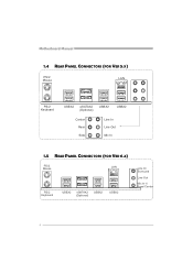
Motherboard Manual 1.4 REAR PANEL CONNECTORS (FOR VER 5.X) PS/2 Mouse LAN PS/2 Keyboard USBX2 eSATAX2 (Optional) USBX2 USBX2 Center Rear Side Line In Line Out Mic In 1.5 REAR PANEL CONNECTORS (FOR VER 6.X) PS/2 Mouse LA N PS/ 2 Ke ybo ar d USB X2 eSATAX2 (Op ti on al) USBX2 USBX2 Line In/ Surround Line Out Mic I n 1/ Bass/ Center 4
Motherboard Manual 1.4 REAR PANEL CONNECTORS (FOR VER 5.X) PS/2 Mouse LAN PS/2 Keyboard USBX2 eSATAX2 (Optional) USBX2 USBX2 Center Rear Side Line In Line Out Mic In 1.5 REAR PANEL CONNECTORS (FOR VER 6.X) PS/2 Mouse LA N PS/ 2 Ke ybo ar d USB X2 eSATAX2 (Op ti on al) USBX2 USBX2 Line In/ Surround Line Out Mic I n 1/ Bass/ Center 4
Setup Manual
Page 8
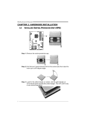
Motherboard Manual CHAPTER 2: HARDWARE INSTALLATION 2.1 INSTALLING CENTRAL PROCESSING UNIT (CPU) Step 1: Remove the socket protection cap. Step 2: Pull the lever toward direction A from the socket and then raise the lever up to a 90-degree angle. The CPU will fit only in the correct orientation. 6 Step 3: Look for the white triangle on socket, and the gold triangle on CPU should point towards this white triangle.
Motherboard Manual CHAPTER 2: HARDWARE INSTALLATION 2.1 INSTALLING CENTRAL PROCESSING UNIT (CPU) Step 1: Remove the socket protection cap. Step 2: Pull the lever toward direction A from the socket and then raise the lever up to a 90-degree angle. The CPU will fit only in the correct orientation. 6 Step 3: Look for the white triangle on socket, and the gold triangle on CPU should point towards this white triangle.
Setup Manual
Page 10
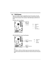
.... The fan cable and connector may be connected to pin#1. Connect the fan cable to the connector while matching the black wire to GND. 8 Motherboard Manual 2.2 FAN HEADERS These fan headers support cooling-fans built in the computer.
.... The fan cable and connector may be connected to pin#1. Connect the fan cable to the connector while matching the black wire to GND. 8 Motherboard Manual 2.2 FAN HEADERS These fan headers support cooling-fans built in the computer.
Setup Manual
Page 12
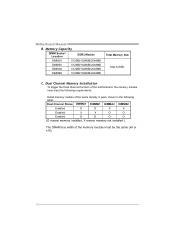
... memory module must meet the following requirements: Install memory module of the motherboard, the memory module must be the same (x8 or x16) 10 Motherboard Manual B. C. Dual Channel Memory installation To trigger the Dual Channel function of the same density in pairs, shown in the following table. Memory Capacity DIMM Socket...
... memory module must meet the following requirements: Install memory module of the motherboard, the memory module must be the same (x8 or x16) 10 Motherboard Manual B. C. Dual Channel Memory installation To trigger the Dual Channel function of the same density in pairs, shown in the following table. Memory Capacity DIMM Socket...
Setup Manual
Page 14
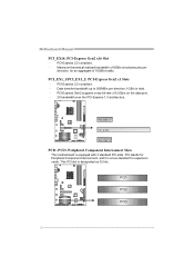
... Gen2 supports a raw bit-rate of 16GB/s totally. This PCI slot is equipped with 3 standard PCI slots. PCI1 PCI2 PCI3 12 PCI-Express 2.0 compliant. - Motherboard Manual PCI_EX16: PCI-Express Gen2 x16 Slot - PCI stands for Peripheral Component Interconnect, and it is a bus standard for an aggregate of 5.0Gb/s on the data...
... Gen2 supports a raw bit-rate of 16GB/s totally. This PCI slot is equipped with 3 standard PCI slots. PCI1 PCI2 PCI3 12 PCI-Express 2.0 compliant. - Motherboard Manual PCI_EX16: PCI-Express Gen2 x16 Slot - PCI stands for Peripheral Component Interconnect, and it is a bus standard for an aggregate of 5.0Gb/s on the data...
Setup Manual
Page 16
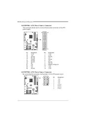
Motherboard Manual JATXPWR1: ATX Power Source Connector This connector allows user to connect 24-pin power connector on the ATX power supply. 12 24 1 13 Pin Assignment ...
Motherboard Manual JATXPWR1: ATX Power Source Connector This connector allows user to connect 24-pin power connector on the ATX power supply. 12 24 1 13 Pin Assignment ...
Setup Manual
Page 18
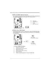
... Pin 1-2 Close: Normal Operation (default). 13 13 Pin 2-3 Close: Clear CMOS data. ※ Clear CMOS Procedures: 1. Remove AC power line. 2. Wait for five seconds. 4. Motherboard Manual JCDIN1: CD-ROM Audio-in Connector This connector allows user to connect the audio source from the variaty devices, like CD-ROM, DVD-ROM, PCI...
... Pin 1-2 Close: Normal Operation (default). 13 13 Pin 2-3 Close: Clear CMOS data. ※ Clear CMOS Procedures: 1. Remove AC power line. 2. Wait for five seconds. 4. Motherboard Manual JCDIN1: CD-ROM Audio-in Connector This connector allows user to connect the audio source from the variaty devices, like CD-ROM, DVD-ROM, PCI...
Setup Manual
Page 20
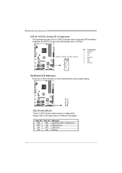
... to show system status. Please refer to SATA Controller with 4 channels SATA interface, it satisfies the SATA 2.0 spec and with transfer rate of 3.0Gb/s. Motherboard Manual SATA1~SATA4: Serial ATA Connectors The motherboard has a PCI to the table below for different messages: LED_D2 OFF OFF ON ON LED_D1 OFF ON OFF...
... to show system status. Please refer to SATA Controller with 4 channels SATA interface, it satisfies the SATA 2.0 spec and with transfer rate of 3.0Gb/s. Motherboard Manual SATA1~SATA4: Serial ATA Connectors The motherboard has a PCI to the table below for different messages: LED_D2 OFF OFF ON ON LED_D1 OFF ON OFF...
Setup Manual
Page 22
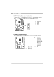
Pin Assignment 1 Carrier detect 2 Received data 3 Transmitted data 4 Data terminal ready 5 Signal ground 6 Data set ready 7 Request to send 8 Clear to send 2 10 9 Ring indicator 10 Key 1 9 20 Motherboard Manual JATXPWR3: Auxiliary Power for Graphics This connector is an auxiliary power connection for the graphics card provides better graphics performance. Exclusive power for graphics cards. Pin Assignment 1 +12V 2 Ground 1 3 Ground 4 VCC 4 JCOM1: Serial port Connector The motherboard has a Serial Port Connector for connecting RS-232 Port.
Pin Assignment 1 Carrier detect 2 Received data 3 Transmitted data 4 Data terminal ready 5 Signal ground 6 Data set ready 7 Request to send 8 Clear to send 2 10 9 Ring indicator 10 Key 1 9 20 Motherboard Manual JATXPWR3: Auxiliary Power for Graphics This connector is an auxiliary power connection for the graphics card provides better graphics performance. Exclusive power for graphics cards. Pin Assignment 1 +12V 2 Ground 1 3 Ground 4 VCC 4 JCOM1: Serial port Connector The motherboard has a Serial Port Connector for connecting RS-232 Port.
Setup Manual
Page 24
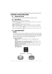
... used in RAID 0 and RAID 1. RAID 1: RAID 1 defines techniques for many applications. RAID 0+1 (eSATA) (Optional): RAID 0+1 combines the techniques used in RAID 0 and RAID 1. Motherboard Manual CHAPTER 4: RAID FUNCTIONS 4.1 OPERATION SYSTEM Supports Windows XP Home/Professional Edition and Windows VISTA. 4.2 RAID ARRAYS RAID supports the following types of RAID arrays: RAID...
... used in RAID 0 and RAID 1. RAID 1: RAID 1 defines techniques for many applications. RAID 0+1 (eSATA) (Optional): RAID 0+1 combines the techniques used in RAID 0 and RAID 1. Motherboard Manual CHAPTER 4: RAID FUNCTIONS 4.1 OPERATION SYSTEM Supports Windows XP Home/Professional Edition and Windows VISTA. 4.2 RAID ARRAYS RAID supports the following types of RAID arrays: RAID...
Setup Manual
Page 25
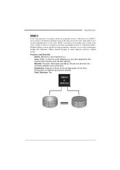
...one drive fail, the controller switches to the other drive. Drawbacks: Requires 2 drives for small databases or any other application that eliminates tedious manual backups to more expensive and less reliable media. RAID 1 provides a hot-standby copy of data if the active volume or drive is corrupted or ..., or as a form of a hardware failure. Block 1 Block 2 Block 3 Block 1 Block 2 Block 3 23 Performance is impaired during drive rebuilds. Fault Tolerance: Yes. TA770 A2+ RAID 1: Every read and write is actually carried out in parallel across 2 disk drives in the array.
...one drive fail, the controller switches to the other drive. Drawbacks: Requires 2 drives for small databases or any other application that eliminates tedious manual backups to more expensive and less reliable media. RAID 1 provides a hot-standby copy of data if the active volume or drive is corrupted or ..., or as a form of a hardware failure. Block 1 Block 2 Block 3 Block 1 Block 2 Block 3 23 Performance is impaired during drive rebuilds. Fault Tolerance: Yes. TA770 A2+ RAID 1: Every read and write is actually carried out in parallel across 2 disk drives in the array.
Setup Manual
Page 26
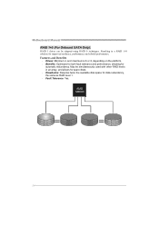
... stripped using RAID 0 techniques. Resulting in an array, and allows for spare disks. Drawbacks: Requires twice the available disk space for automatic redundancy. Motherboard Manual RAID 1+0 (For Onboard SATA Only): RAID 1 drives can be simultaneously used with other RAID levels in a RAID 1+0 solution for improved resiliency, performance and rebuild performance...
... stripped using RAID 0 techniques. Resulting in an array, and allows for spare disks. Drawbacks: Requires twice the available disk space for automatic redundancy. Motherboard Manual RAID 1+0 (For Onboard SATA Only): RAID 1 drives can be simultaneously used with other RAID levels in a RAID 1+0 solution for improved resiliency, performance and rebuild performance...
Setup Manual
Page 28
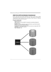
... 5 DATA 8 PARITY DATA 11 Disk 3 PARITY DATA 4 DATA 6 PARITY DATA 10 DATA 12 26 Write performance can be CPU intensive. Fault Tolerance: Yes. Motherboard Manual RAID 5 (For eSATA with Multiplier Only)(Optional): RAID 5 stripes both data and parity information across all the drives in the array. It writes data and...
... 5 DATA 8 PARITY DATA 11 Disk 3 PARITY DATA 4 DATA 6 PARITY DATA 10 DATA 12 26 Write performance can be CPU intensive. Fault Tolerance: Yes. Motherboard Manual RAID 5 (For eSATA with Multiplier Only)(Optional): RAID 5 stripes both data and parity information across all the drives in the array. It writes data and...
Setup Manual
Page 29
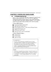
... reference only and the actual BIOS information and settings on many precise tests, Biostar Engineering Team (BET) has developed this ultimate overclock engine to the BIOS Manual in this manual. The BIOS information described below in the Setup CD. For further information of... Self Recovery System (S.R.S) Smart Fan Function (under BIOS or Windows interface, T-Power is being continuously updated. TA770 A2+ CHAPTER 5: OVERCLOCK QUICK GUIDE 5.1 T-POWER INTRODUCTION Biostar T-Power is a whole new utility that is not recommended for inexperienced users. We also would not guarantee ...
... reference only and the actual BIOS information and settings on many precise tests, Biostar Engineering Team (BET) has developed this ultimate overclock engine to the BIOS Manual in this manual. The BIOS information described below in the Setup CD. For further information of... Self Recovery System (S.R.S) Smart Fan Function (under BIOS or Windows interface, T-Power is being continuously updated. TA770 A2+ CHAPTER 5: OVERCLOCK QUICK GUIDE 5.1 T-POWER INTRODUCTION Biostar T-Power is a whole new utility that is not recommended for inexperienced users. We also would not guarantee ...
Setup Manual
Page 30
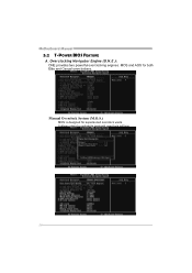
It allows users to customize personal overclock settings. 28 Manual Overclock System (M.O.S.) MOS is designed for both Elite and Casual overclockers. Overclocking Navigator Engine (O.N.E.): ONE provides two powerful overclocking engines: MOS and AOS for experienced overclock users. Motherboard Manual 5.2 T-POWER BIOS FEATURE A.
It allows users to customize personal overclock settings. 28 Manual Overclock System (M.O.S.) MOS is designed for both Elite and Casual overclockers. Overclocking Navigator Engine (O.N.E.): ONE provides two powerful overclocking engines: MOS and AOS for experienced overclock users. Motherboard Manual 5.2 T-POWER BIOS FEATURE A.
Setup Manual
Page 32
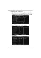
Based on many tests and experiments, A.O.S. V6 Tech Engine: This engine will make a good over -clock performance. 30 V8 Tech Engine: This engine will make a better over -clock performance. Motherboard Manual Automatic Overclock System (A.O.S.) For beginners in a single step. provides 3 ideal overclock configurations that are able to raise the system performance in overclock field, BET had developed an easy, fast, and powerful feature to increase the system performance, named A.O.S.
Based on many tests and experiments, A.O.S. V6 Tech Engine: This engine will make a good over -clock performance. 30 V8 Tech Engine: This engine will make a better over -clock performance. Motherboard Manual Automatic Overclock System (A.O.S.) For beginners in a single step. provides 3 ideal overclock configurations that are able to raise the system performance in overclock field, BET had developed an easy, fast, and powerful feature to increase the system performance, named A.O.S.
Setup Manual
Page 34
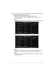
MIT allows users to ensure the memory stability. Motherboard Manual C. the condition parameter should be changed to "Enable" to complete the test. 32 Step 3: When the process is done, change the setting back from CMOS ...
MIT allows users to ensure the memory stability. Motherboard Manual C. the condition parameter should be changed to "Enable" to complete the test. 32 Step 3: When the process is done, change the setting back from CMOS ...

