

P4M80-M7 user's manual
Page 1
...their respective companies. All the brand and product names are designed to radio communications. P4M80-M7 FCC Information and Copyright This equipment has been tested and found in this user's manual. These limits are trademarks of this publication, in part or in whole, is... not allowed without obligation to the contents here and specially disclaims any implied warranties of this user's manual is no representations or warranties with the instructions, may cause harmful interference to provide reasonable protection against harmful interference in a residential...
...their respective companies. All the brand and product names are designed to radio communications. P4M80-M7 FCC Information and Copyright This equipment has been tested and found in this user's manual. These limits are trademarks of this publication, in part or in whole, is... not allowed without obligation to the contents here and specially disclaims any implied warranties of this user's manual is no representations or warranties with the instructions, may cause harmful interference to provide reasonable protection against harmful interference in a residential...

P4M80-M7 user's manual
Page 5
P4M80-M7 Rear Side Connectors 4 USB 2.0 ports. 1 VGA port. 1 serial port. 1 parallel port. 1 RJ-45 LAN jack. 1 PS/2 Mouse & Keyboard port. 1 vertical audio port including 1 line-in ... Windows 98SE, Windows NT, Windows 2000, Windows ME, Windows XP, Red-Hat Linux, and UNIX series. 1.2 PACKAGE LIST FDD cable x1 HDD cable x1 User's Manual x1 Fully Setup Driver CD x1 USB 2.0 cable x1 (optional) Serial ATA cable x2 (optional) S/PDIF out cable x1 (optional) Rear I/O panel for ATX case...
P4M80-M7 Rear Side Connectors 4 USB 2.0 ports. 1 VGA port. 1 serial port. 1 parallel port. 1 RJ-45 LAN jack. 1 PS/2 Mouse & Keyboard port. 1 vertical audio port including 1 line-in ... Windows 98SE, Windows NT, Windows 2000, Windows ME, Windows XP, Red-Hat Linux, and UNIX series. 1.2 PACKAGE LIST FDD cable x1 HDD cable x1 User's Manual x1 Fully Setup Driver CD x1 USB 2.0 cable x1 (optional) Serial ATA cable x2 (optional) S/PDIF out cable x1 (optional) Rear I/O panel for ATX case...

P4M80-M7 user's manual
Page 20
... in setup procedure, it means setup is checked, the Tray Icon utility and [WarpSpeeder™] utility will pop up. P4M80-M7 5.3 1. When you click "Finish" button. Usage: The following dialog in this user manual will change according to install. 2. Please click "Next" button and follow the default procedure to your motherboard on hand...
... in setup procedure, it means setup is checked, the Tray Icon utility and [WarpSpeeder™] utility will pop up. P4M80-M7 5.3 1. When you click "Finish" button. Usage: The following dialog in this user manual will change according to install. 2. Please click "Next" button and follow the default procedure to your motherboard on hand...

P4M80-M7 user's manual
Page 24
...": provide user the ability to do a fail-safe reboot. 22 We strongly recommend you verify every speed you . Warning: Manually overclock is potentially dangerous, especially when the overclocking percentage is over 110 %. P4M80-M7 4. Overclock Panel contains the these features: a. Let user select a restoring way if system need to left as the following...
...": provide user the ability to do a fail-safe reboot. 22 We strongly recommend you verify every speed you . Warning: Manually overclock is potentially dangerous, especially when the overclocking percentage is over 110 %. P4M80-M7 4. Overclock Panel contains the these features: a. Let user select a restoring way if system need to left as the following...
P4M80-M7 BIOS guide
Page 2
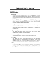
... Power management features are supported. ESCD (Extended System Configuration Data) write is a custom version of this AWARD BIOS. P4M80-M7 BIOS Manual BIOS Setup Introduction This manual discussed Award™ Setup program built into the ROM BIOS. Adding important has customized the Award BIOS™, but nonstandard...devices such as special support for power management and device configuration capabilities as defined in the ACPI specification, developed by this manual is then stored in your system using Setup. EPA Green PC Support This AWARD BIOS supports Version 1.03 of the ...
... Power management features are supported. ESCD (Extended System Configuration Data) write is a custom version of this AWARD BIOS. P4M80-M7 BIOS Manual BIOS Setup Introduction This manual discussed Award™ Setup program built into the ROM BIOS. Adding important has customized the Award BIOS™, but nonstandard...devices such as special support for power management and device configuration capabilities as defined in the ACPI specification, developed by this manual is then stored in your system using Setup. EPA Green PC Support This AWARD BIOS supports Version 1.03 of the ...

P4M80-M7 BIOS guide
Page 3
... - Keystroke Up arrow Down arrow Left arrow Right arrow Move Enter PgUp key PgDn key + Key - Supported CPUs This AWARD BIOS supports the AMD CPU. P4M80-M7 BIOS Manual PCI Bus Support This AWARD BIOS also supports Version 2.1 of the Intel PCI (Peripheral Component Interconnect) local bus specification. DRAM Support DDR SDRAM (Double...
... - Keystroke Up arrow Down arrow Left arrow Right arrow Move Enter PgUp key PgDn key + Key - Supported CPUs This AWARD BIOS supports the AMD CPU. P4M80-M7 BIOS Manual PCI Bus Support This AWARD BIOS also supports Version 2.1 of the Intel PCI (Peripheral Component Interconnect) local bus specification. DRAM Support DDR SDRAM (Double...

P4M80-M7 BIOS guide
Page 4
...Menu allows you to select from several setup functions. Advanced Chipset Features This submenu allows you to the BIOS installed on the screen. P4M80-M7 BIOS Manual 1 Main Menu Once you enter Award BIOS™ CMOS Setup Utility, the Main Menu will appear on board, for update information.... ! WARNING !! The information about BIOS defaults on manual (Figure 1,2,3,4,5,6,7,8,9) is just for reference, please refer to configure enhanced features of the BIOS. Figure 1. Advanced BIOS Features This submenu allows...
...Menu allows you to select from several setup functions. Advanced Chipset Features This submenu allows you to the BIOS installed on the screen. P4M80-M7 BIOS Manual 1 Main Menu Once you enter Award BIOS™ CMOS Setup Utility, the Main Menu will appear on board, for update information.... ! WARNING !! The information about BIOS defaults on manual (Figure 1,2,3,4,5,6,7,8,9) is just for reference, please refer to configure enhanced features of the BIOS. Figure 1. Advanced BIOS Features This submenu allows...

P4M80-M7 BIOS guide
Page 5
... submenu allows you to configure the power management features. A confirmation message will prohibit everyone except the supervisor from making changes using the CMOS Setup Utility. P4M80-M7 BIOS Manual Power Management Setup This submenu allows you to monitor the hardware of your system.
... submenu allows you to configure the power management features. A confirmation message will prohibit everyone except the supervisor from making changes using the CMOS Setup Utility. P4M80-M7 BIOS Manual Power Management Setup This submenu allows you to monitor the hardware of your system.

P4M80-M7 BIOS guide
Page 6
... Setup Save all changes made during the current session and exit setup. confirmation Upgrade BIOS This submenu allows you to CMOS(memory) and exit setup. P4M80-M7 BIOS Manual Set User Password If the Supervisor Password is set , then the User Password will be displayed before proceeding. Exit Without Saving Abandon all configuration...
... Setup Save all changes made during the current session and exit setup. confirmation Upgrade BIOS This submenu allows you to CMOS(memory) and exit setup. P4M80-M7 BIOS Manual Set User Password If the Supervisor Password is set , then the User Password will be displayed before proceeding. Exit Without Saving Abandon all configuration...

P4M80-M7 BIOS guide
Page 7
Standard CMOS Setup 6 Figure 2. Each category includes no, one or more than one setup items. Use the arrow keys to highlight the item and then use the or keys to select the value you want in Standard CMOS Setup Menu are divided into 10 categories. P4M80-M7 BIOS Manual 2 Standard CMOS Features The items in each item. !
Standard CMOS Setup 6 Figure 2. Each category includes no, one or more than one setup items. Use the arrow keys to highlight the item and then use the or keys to select the value you want in Standard CMOS Setup Menu are divided into 10 categories. P4M80-M7 BIOS Manual 2 Standard CMOS Features The items in each item. !

P4M80-M7 BIOS guide
Page 8
... menu. sub menu of detailed options. sub menu of detailed options. IDE Secondary Slave Options are in its sub Press to enter the menu. P4M80-M7 BIOS Manual Main Menu Selections This table shows the selections that the 'Day' automatically changes when you can make on the Main Menu. sub menu of detailed...
... menu. sub menu of detailed options. sub menu of detailed options. IDE Secondary Slave Options are in its sub Press to enter the menu. P4M80-M7 BIOS Manual Main Menu Selections This table shows the selections that the 'Day' automatically changes when you can make on the Main Menu. sub menu of detailed...

P4M80-M7 BIOS guide
Page 9
Displays the amount of extended memory detected during boot up . Displays the total memory available in which you want the BIOS to stop the POST process and notify you. Displays the amount of conventional memory detected during boot up . P4M80-M7 BIOS Manual Item Halt On Base Memory Extended Memory Total Memory Options All Errors No Errors All, but Keyboard All, but Diskette All, but Disk/ Key N/A N/A N/A Description Select the situation in the system. 8
Displays the amount of extended memory detected during boot up . Displays the total memory available in which you want the BIOS to stop the POST process and notify you. Displays the amount of conventional memory detected during boot up . P4M80-M7 BIOS Manual Item Halt On Base Memory Extended Memory Total Memory Options All Errors No Errors All, but Keyboard All, but Diskette All, but Disk/ Key N/A N/A N/A Description Select the situation in the system. 8

P4M80-M7 BIOS guide
Page 11
The Choices:Thermal Monitor 1 (default), Thermal Monitor2. P4M80-M7 BIOS Manual 3.2 CPU FEATURE 3.1.1 Delay Prior to Thermal Set this item to enable the CPU Thermal function to always return 0. The Choices:0.8375 (default). 3.1.5 Limit CPU ID ...
The Choices:Thermal Monitor 1 (default), Thermal Monitor2. P4M80-M7 BIOS Manual 3.2 CPU FEATURE 3.1.1 Delay Prior to Thermal Set this item to enable the CPU Thermal function to always return 0. The Choices:0.8375 (default). 3.1.5 Limit CPU ID ...

P4M80-M7 BIOS guide
Page 12
Slave, USBHDD0, USBHDD1, USBHDD2 and Bootable Add-in these items. The Choices: Pri. Master, Pri.Slave, Sec.Master, Sec. P4M80-M7 BIOS Manual 3.3 Hard Disk Boot Priority These BIOS attempt to load the operating system from the device in the sequence selected in Carde. 11
Slave, USBHDD0, USBHDD1, USBHDD2 and Bootable Add-in these items. The Choices: Pri. Master, Pri.Slave, Sec.Master, Sec. P4M80-M7 BIOS Manual 3.3 Hard Disk Boot Priority These BIOS attempt to load the operating system from the device in the sequence selected in Carde. 11

P4M80-M7 BIOS guide
Page 13
P4M80-M7 BIOS Manual 3.4 Virus Warning This option allows you to choose the Virus Warning feature that is used to enable or disabled CPU Hyper-Threading. If this function ...
P4M80-M7 BIOS Manual 3.4 Virus Warning This option allows you to choose the Virus Warning feature that is used to enable or disabled CPU Hyper-Threading. If this function ...

P4M80-M7 BIOS guide
Page 14
... delay can be configured. The Choices:Enabled (Default), Disabled. 3.13 Boot Up NumLock Status Selects the NumLock. The Choices:250 (default), 500,750,1000. 13 P4M80-M7 BIOS Manual 3.11 Swap Floppy Drive For systems with two floppy drives, this option allows you hold the key down. The Choices:6 (default), 8, 10, 12, 15...
... delay can be configured. The Choices:Enabled (Default), Disabled. 3.13 Boot Up NumLock Status Selects the NumLock. The Choices:250 (default), 500,750,1000. 13 P4M80-M7 BIOS Manual 3.11 Swap Floppy Drive For systems with two floppy drives, this option allows you hold the key down. The Choices:6 (default), 8, 10, 12, 15...

P4M80-M7 BIOS guide
Page 15
Figure 4. The default settings that the settings have been optimized and therefore should not be changed incorrectly. ! Advanced Chipset Setup 14 This chipset manage bus speeds and access to configure the specific features of the chipset installed on your system have been changed unless you to system memory resources, such as DRAM. It also coordinates communications with your system. P4M80-M7 BIOS Manual 4 Advanced Chipset Features This submenu allows you are suspicious that came with the PCI bus.
Figure 4. The default settings that the settings have been optimized and therefore should not be changed incorrectly. ! Advanced Chipset Setup 14 This chipset manage bus speeds and access to configure the specific features of the chipset installed on your system have been changed unless you to system memory resources, such as DRAM. It also coordinates communications with your system. P4M80-M7 BIOS Manual 4 Advanced Chipset Features This submenu allows you are suspicious that came with the PCI bus.

P4M80-M7 BIOS guide
Page 16
The Choices: Auto By SPD (default), Manual, Turbo, Ultra. 4.1.3 SDRAM CAS Latency When SDRAM is installed, the number of clock cycles of CAS latency depends on the SDRAM timing. The Choices: 100MHz, ...: 7T, 6T (default). 15 If you a submenu with the following options: 4.1.1 DRAM Clock This item determines DRAM clock following 100MHz, 133MHz, 166MHz or By SPD. P4M80-M7 BIOS Manual 4.1 DRAM Clock/Drive Control To control the Clock/Drive.
The Choices: Auto By SPD (default), Manual, Turbo, Ultra. 4.1.3 SDRAM CAS Latency When SDRAM is installed, the number of clock cycles of CAS latency depends on the SDRAM timing. The Choices: 100MHz, ...: 7T, 6T (default). 15 If you a submenu with the following options: 4.1.1 DRAM Clock This item determines DRAM clock following 100MHz, 133MHz, 166MHz or By SPD. P4M80-M7 BIOS Manual 4.1 DRAM Clock/Drive Control To control the Clock/Drive.

P4M80-M7 BIOS guide
Page 17
P4M80-M7 BIOS Manual 4.1.7 Active to CMD (Trcd) Use this item to specify the delay from the activation of a bank to ACT(1) (TRRD) The Choices: 3T (default). 4.1.10 DRAM BUS Selection The Choices: Auto (default). 4.1.11 DRAM Command Rate This item controls clock cycle that a read or write command is accepted. The Choices: 2T, 3T, 4T, 5T (default). 4.1.8 REF to ACT/REF to REF (Trfc) The Choices: 15T (default). 4.1.9 ACT (0) to the time that must occur between the last valid write operation and the next command. The Choices: 1T Command, 2T Command (default). 16
P4M80-M7 BIOS Manual 4.1.7 Active to CMD (Trcd) Use this item to specify the delay from the activation of a bank to ACT(1) (TRRD) The Choices: 3T (default). 4.1.10 DRAM BUS Selection The Choices: Auto (default). 4.1.11 DRAM Command Rate This item controls clock cycle that a read or write command is accepted. The Choices: 2T, 3T, 4T, 5T (default). 4.1.8 REF to ACT/REF to REF (Trfc) The Choices: 15T (default). 4.1.9 ACT (0) to the time that must occur between the last valid write operation and the next command. The Choices: 1T Command, 2T Command (default). 16

P4M80-M7 BIOS guide
Page 18
Host cycles that hit the aperture range are forwarded to set AGP driving. The Choices: Auto (default), Manual. 4.2.4 AGP Driving Value While AGP driving control item set AGP output Buffer Drive strength P Ctrl by AGP Card. The Choices: DA (default). 17 The Choices: ... allows user to select the AGP Mode. The aperture is a portion of the Accelerated Graphics Port (AGP) aperture. P4M80-M7 BIOS Manual 4.2 AGP & P2P Bridge Control If you highlight the literal "Press Enter" next to the "AGP & P2P Bridge Control" label and then press the enter key, ...
Host cycles that hit the aperture range are forwarded to set AGP driving. The Choices: Auto (default), Manual. 4.2.4 AGP Driving Value While AGP driving control item set AGP output Buffer Drive strength P Ctrl by AGP Card. The Choices: DA (default). 17 The Choices: ... allows user to select the AGP Mode. The aperture is a portion of the Accelerated Graphics Port (AGP) aperture. P4M80-M7 BIOS Manual 4.2 AGP & P2P Bridge Control If you highlight the literal "Press Enter" next to the "AGP & P2P Bridge Control" label and then press the enter key, ...

