Setup Manual
Page 1
MCP6P3/N68S3 Setup Manual FCC Information and Copyright This equipment has been tested and found ...provide reasonable protection against harmful interference in writing. Further the vendor reserves the right to revise this user's manual is subject to be changed without notice and we will not occur in a particular installation. All the ...to the contents here without first obtaining the vendor's approval in a residential installation. The content of this user's manual. These limits are trademarks of the FCC Rules. This equipment generates, uses, and can radiate radio frequency energy ...
MCP6P3/N68S3 Setup Manual FCC Information and Copyright This equipment has been tested and found ...provide reasonable protection against harmful interference in writing. Further the vendor reserves the right to revise this user's manual is subject to be changed without notice and we will not occur in a particular installation. All the ...to the contents here without first obtaining the vendor's approval in a residential installation. The content of this user's manual. These limits are trademarks of the FCC Rules. This equipment generates, uses, and can radiate radio frequency energy ...
Setup Manual
Page 3
...installing the motherboard, please make sure you for ATX Case X 1 Installation Guide X 1 Fully Setup Driver CD X 1 (full version manual files inside the case after installation. Hold the board on motherboard or the rear side of the computer should be 0 to 45 degrees ...Power Cable X 1 (optional) USB 2.0 Cable X1 (optional) S/PDIF out Cable X 1 (optional) Note: The package contents may damage the equipment. CHAPTER 1: INTRODUCTION MCP6P3/N68S3 1.1 BEFORE YOU START Thank you follow the instructions below: Prepare a dry and stable working environment with sufficient lighting.
...installing the motherboard, please make sure you for ATX Case X 1 Installation Guide X 1 Fully Setup Driver CD X 1 (full version manual files inside the case after installation. Hold the board on motherboard or the rear side of the computer should be 0 to 45 degrees ...Power Cable X 1 (optional) USB 2.0 Cable X1 (optional) S/PDIF out Cable X 1 (optional) Note: The package contents may damage the equipment. CHAPTER 1: INTRODUCTION MCP6P3/N68S3 1.1 BEFORE YOU START Thank you follow the instructions below: Prepare a dry and stable working environment with sufficient lighting.
Setup Manual
Page 4
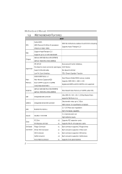
...Manual 1.3 MOTHERBOARD FEATURES SPEC Socket AM3 AMD 64 Architecture enables 32 and 64 bit computing CPU AMD Phenom II/ Athlon II processors Supports Hyper Transport 2.0 (Maximum Watt: 95W) Support HyperTransport 2.0 FSB Supports up to 2.0 GT/s Bandwidth Chipset GeForce 6150 SE/nForce 430 (MCP6P3) GeForce 7025/nForce 630a (N68S3.../ 1066 / 1333 Registered DIMM and ECC DIMM is not supported Graphics GeForce 6150 SE/nForce 430 (MCP6P3) GeForce 7025/nForce 630a (N68S3) Max Shared Video Memory is 512MB (under OS) IDE Integrated IDE Controller Ultra DMA 33 / 66 / 100 / 133 Bus Master...
...Manual 1.3 MOTHERBOARD FEATURES SPEC Socket AM3 AMD 64 Architecture enables 32 and 64 bit computing CPU AMD Phenom II/ Athlon II processors Supports Hyper Transport 2.0 (Maximum Watt: 95W) Support HyperTransport 2.0 FSB Supports up to 2.0 GT/s Bandwidth Chipset GeForce 6150 SE/nForce 430 (MCP6P3) GeForce 7025/nForce 630a (N68S3.../ 1066 / 1333 Registered DIMM and ECC DIMM is not supported Graphics GeForce 6150 SE/nForce 430 (MCP6P3) GeForce 7025/nForce 630a (N68S3) Max Shared Video Memory is 512MB (under OS) IDE Integrated IDE Controller Ultra DMA 33 / 66 / 100 / 133 Bus Master...

Setup Manual
Page 6
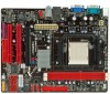
Super I/O JUS B V2 IDE1 F_USB2 F_USB1 BIOS JCMOS1 SATA2 SATA4 SATA1 SATA3 S YS_FAN1 PANEL1 4 Motherboard Manual 1.5 MOTHERBOARD LAYOUT KBMS1 AT X P W R2 JK B _P WR CP U_FAN1 COM1 DDR3_A1 DDR3_B1 Socket AM3 VGA1 USB1 RJ45USB1 JUS B V 1 AT X P WR1 AUDIO1 F _ A UDIO 1 -"/ BAT1 GeForce 6150 SE/7025 nForce 430/630a PEX16_1 PCI1 Codec JP RINT 1 PCI2 FDD1 JS P DIF O UT 1 Note: ■ represents the 1st pin.
Super I/O JUS B V2 IDE1 F_USB2 F_USB1 BIOS JCMOS1 SATA2 SATA4 SATA1 SATA3 S YS_FAN1 PANEL1 4 Motherboard Manual 1.5 MOTHERBOARD LAYOUT KBMS1 AT X P W R2 JK B _P WR CP U_FAN1 COM1 DDR3_A1 DDR3_B1 Socket AM3 VGA1 USB1 RJ45USB1 JUS B V 1 AT X P WR1 AUDIO1 F _ A UDIO 1 -"/ BAT1 GeForce 6150 SE/7025 nForce 430/630a PEX16_1 PCI1 Codec JP RINT 1 PCI2 FDD1 JS P DIF O UT 1 Note: ■ represents the 1st pin.

Setup Manual
Page 8
This completes the installation. 6 Connect the CPU FAN power cable to complete the installation. Step 4: Put the CPU Fan on the CPU and buckle it. Motherboard Manual Step 3: Hold the CPU down firmly, and then close the lever toward direct B to the CPU_FAN1.
This completes the installation. 6 Connect the CPU FAN power cable to complete the installation. Step 4: Put the CPU Fan on the CPU and buckle it. Motherboard Manual Step 3: Hold the CPU down firmly, and then close the lever toward direct B to the CPU_FAN1.

Setup Manual
Page 10
Unlock a DIMM slot by pressing the retaining clips outward. Align a DIMM on the slot such that the notch on the DIMM matches the break on the Slot. 2. Memory Modules 1. Insert the DIMM vertically and firmly into the slot until the retaining chip snap back in place and the DIMM is properly seated. 8 D D R3 _A 1 D D R3 _B 1 Motherboard Manual 2.3 INSTALLING SYSTEM MEMORY A.
Unlock a DIMM slot by pressing the retaining clips outward. Align a DIMM on the slot such that the notch on the DIMM matches the break on the Slot. 2. Memory Modules 1. Insert the DIMM vertically and firmly into the slot until the retaining chip snap back in place and the DIMM is properly seated. 8 D D R3 _A 1 D D R3 _B 1 Motherboard Manual 2.3 INSTALLING SYSTEM MEMORY A.
Setup Manual
Page 12
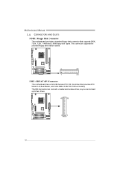
The IDE connector can connect a master and a slave drive, so you can connect up to two drives. 40 39 2 1 10 Motherboard Manual 2.4 CONNECTORS AND SLOTS FDD1: Floppy Disk Connector The motherboard provides a standard floppy disk connector that provides PIO Mode 0~4, Bus Master, and Ultra DMA 33/66/100/133 functionality. This connector supports the provided floppy drive ribbon cables. 2 34 1 33 IDE1: IDE/ATAPI Connector The motherboard has a 32-bit Enhanced PCI IDE Controller that supports 360K, 720K, 1.2M, 1.44M and 2.88M floppy disk types.
The IDE connector can connect a master and a slave drive, so you can connect up to two drives. 40 39 2 1 10 Motherboard Manual 2.4 CONNECTORS AND SLOTS FDD1: Floppy Disk Connector The motherboard provides a standard floppy disk connector that provides PIO Mode 0~4, Bus Master, and Ultra DMA 33/66/100/133 functionality. This connector supports the provided floppy drive ribbon cables. 2 34 1 33 IDE1: IDE/ATAPI Connector The motherboard has a 32-bit Enhanced PCI IDE Controller that supports 360K, 720K, 1.2M, 1.44M and 2.88M floppy disk types.

Setup Manual
Page 14
Motherboard Manual ATXPWR2: ATX Power Source Connector Connecting this connector provides +12V to CPU power circuit. 1 4 2 3 Pin Assignment 1 +12V 2 +12V 3 Ground 4 Ground Note: Before you power on ...
Motherboard Manual ATXPWR2: ATX Power Source Connector Connecting this connector provides +12V to CPU power circuit. 1 4 2 3 Pin Assignment 1 +12V 2 +12V 3 Ground 4 Ground Note: Before you power on ...
Setup Manual
Page 16
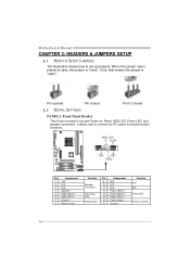
..., and speaker connection. Pin opened Pin closed Pin1-2 closed 3.2 DETAIL SETTINGS PANEL1: Front Panel Header This 16-pin connector includes Power-on button 14 Motherboard Manual CHAPTER 3: HEADERS & JUMPERS SETUP 3.1 HOW TO SETUP JUMPERS The illustration shows how to connect the PC case's front panel switch functions. When the jumper cap...
..., and speaker connection. Pin opened Pin closed Pin1-2 closed 3.2 DETAIL SETTINGS PANEL1: Front Panel Header This 16-pin connector includes Power-on button 14 Motherboard Manual CHAPTER 3: HEADERS & JUMPERS SETUP 3.1 HOW TO SETUP JUMPERS The illustration shows how to connect the PC case's front panel switch functions. When the jumper cap...

Setup Manual
Page 18
Motherboard Manual F_AUDIO1: Front Panel Audio Header This header allows user to connect the PCI bracket SPDIF output header. 13 Pin Assignment 1 +5V 2 SPDIF_OUT 3 Ground 16 This header allows only HD audio front panel connector; AC'97 connector is not acceptable. 2 10 1 9 Pin Assignment 1 Mic Left in 2 Ground 3 Mic Right in 4 GPIO 5 Right line in 6 Jack Sense 7 Front Sense 8 Key 9 Left line in 10 Jack Sense JSPDIFOUT1: Digital Audio-out Connector This connector allows user to connect the front audio output cable with the PC front panel.
Motherboard Manual F_AUDIO1: Front Panel Audio Header This header allows user to connect the PCI bracket SPDIF output header. 13 Pin Assignment 1 +5V 2 SPDIF_OUT 3 Ground 16 This header allows only HD audio front panel connector; AC'97 connector is not acceptable. 2 10 1 9 Pin Assignment 1 Mic Left in 2 Ground 3 Mic Right in 4 GPIO 5 Right line in 6 Jack Sense 7 Front Sense 8 Key 9 Left line in 10 Jack Sense JSPDIFOUT1: Digital Audio-out Connector This connector allows user to connect the front audio output cable with the PC front panel.

Setup Manual
Page 20
JUSBV2: +5V for USB ports at F_USB1/F_USB2. JUSBV1 3 1 3 1 JUSBV2 3 1 Pin 1-2 close 3 1 Pin 2-3 close JKB_PWR: Power Source Header for PS/2 Keyboard and Mouse 3 3 1 1 Pin 1-2 close +5V for PS/2 keyboard and mouse. 3 1 Pin 2-3 close +5V STB for PS/2 keyboard and mouse. 18 JUSBV2: +5V STB for USB ports at F_USB1/F_USB2. Pin 2-3 Close: JUSBV1: +5V STB for USB ports at USB1/RJ45USB1. Motherboard Manual JUSBV1/JUSBV2: Power Source Headers for USB Ports Pin 1-2 Close: JUSBV1: +5V for USB ports at USB1/RJ45USB1.
JUSBV2: +5V for USB ports at F_USB1/F_USB2. JUSBV1 3 1 3 1 JUSBV2 3 1 Pin 1-2 close 3 1 Pin 2-3 close JKB_PWR: Power Source Header for PS/2 Keyboard and Mouse 3 3 1 1 Pin 1-2 close +5V for PS/2 keyboard and mouse. 3 1 Pin 2-3 close +5V STB for PS/2 keyboard and mouse. 18 JUSBV2: +5V STB for USB ports at F_USB1/F_USB2. Pin 2-3 Close: JUSBV1: +5V STB for USB ports at USB1/RJ45USB1. Motherboard Manual JUSBV1/JUSBV2: Power Source Headers for USB Ports Pin 1-2 Close: JUSBV1: +5V for USB ports at USB1/RJ45USB1.
Setup Manual
Page 22
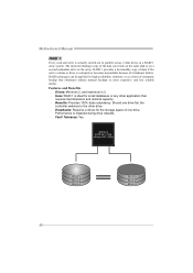
... can be applied for the storage space of one drive fail, the controller switches to the other application that eliminates tedious manual backups to more expensive and less reliable media. Motherboard Manual RAID 1: Every read and write is actually carried out in parallel across 2 disk drives in the array. Features and Benefits...
... can be applied for the storage space of one drive fail, the controller switches to the other application that eliminates tedious manual backups to more expensive and less reliable media. Motherboard Manual RAID 1: Every read and write is actually carried out in parallel across 2 disk drives in the array. Features and Benefits...

Setup Manual
Page 24
... nForce 430 / 630a Disk 2 DATA 2 PARITY DATA 5 DATA 8 PARITY DATA 11 Disk 3 PARITY DATA 4 DATA 6 PARITY DATA 10 DATA 12 ※ For more drives. Motherboard Manual RAID 5: RAID 5 stripes both data and parity information across all the drives in the array. Write performance can be CPU intensive. Fault Tolerance: Yes...
... nForce 430 / 630a Disk 2 DATA 2 PARITY DATA 5 DATA 8 PARITY DATA 11 Disk 3 PARITY DATA 4 DATA 6 PARITY DATA 10 DATA 12 ※ For more drives. Motherboard Manual RAID 5: RAID 5 stripes both data and parity information across all the drives in the array. Write performance can be CPU intensive. Fault Tolerance: Yes...
Setup Manual
Page 25
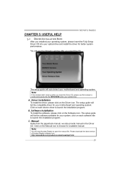
... Installation To install the software, please click on the Driver icon. Manual Aside from http://www.adobe.com/products/acrobat/readstep2.html 23 Note: You will need Acrobat Reader to launch the installation program. C. B. MCP6P3/N68S3 CHAPTER 5: USEFUL HELP 5.1 DRIVER INSTALLATION NOTE After you insert the CD The setup guide will auto...
... Installation To install the software, please click on the Driver icon. Manual Aside from http://www.adobe.com/products/acrobat/readstep2.html 23 Note: You will need Acrobat Reader to launch the installation program. C. B. MCP6P3/N68S3 CHAPTER 5: USEFUL HELP 5.1 DRIVER INSTALLATION NOTE After you insert the CD The setup guide will auto...
Setup Manual
Page 26
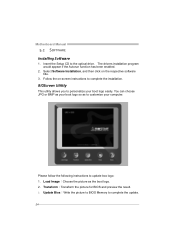
.... The drivers installation program would appear if the Autorun function has been enabled. 2. Transform:Transform the picture for BIOS and preview the result. 3. Motherboard Manual 5.2 SOFTWARE Installing Software 1. BIOScreen Utility This utility allows you to the optical drive.
.... The drivers installation program would appear if the Autorun function has been enabled. 2. Transform:Transform the picture for BIOS and preview the result. 3. Motherboard Manual 5.2 SOFTWARE Installing Software 1. BIOScreen Utility This utility allows you to the optical drive.

Setup Manual
Page 28
... the CPU surface. 2. CPU fan is placed evenly with the CPU speed. Wait for seconds, that means the CPU protection function has been activated. Motherboard Manual 5.4 EXTRA INFORMATION CPU Overheated If the system shutdown automatically after power on system for seconds. 3. CPU fan speed is over heated, the motherboard will shutdown...
... the CPU surface. 2. CPU fan is placed evenly with the CPU speed. Wait for seconds, that means the CPU protection function has been activated. Motherboard Manual 5.4 EXTRA INFORMATION CPU Overheated If the system shutdown automatically after power on system for seconds. 3. CPU fan speed is over heated, the motherboard will shutdown...

Setup Manual
Page 46
Motherboard Manual JAPANESE 仕様 Socket AM3 AMD 64 32ビットと64 CPU AMD Phenom II/ Athlon II 能です 95W) 2.0 2.0 GT/s FSB ート2.0 GeForce 6150 SE/nForce 430 (MCP6P3 GeForce 7025/nForce 630a (N68S3) DDR3 DIMM x 2... 8718F Super I/O H/Wモニター Super I/O ITE GeForce 6150 SE/nForce 430 (MCP6P3) ス GeForce 7025/nForce 630a (N68S3) 512MBです(under OS) IDE 統合IDE Ultra DMA 33 / 66 / 100 / 133 PIO Mode 0~4 SATA II ...
Motherboard Manual JAPANESE 仕様 Socket AM3 AMD 64 32ビットと64 CPU AMD Phenom II/ Athlon II 能です 95W) 2.0 2.0 GT/s FSB ート2.0 GeForce 6150 SE/nForce 430 (MCP6P3 GeForce 7025/nForce 630a (N68S3) DDR3 DIMM x 2... 8718F Super I/O H/Wモニター Super I/O ITE GeForce 6150 SE/nForce 430 (MCP6P3) ス GeForce 7025/nForce 630a (N68S3) 512MBです(under OS) IDE 統合IDE Ultra DMA 33 / 66 / 100 / 133 PIO Mode 0~4 SATA II ...
Bios Manual
Page 1
MCP6P3/N68S3 BIOS Manual BIOS Setup 1 1 Main Menu 3 2 Advanced Menu 7 3 PCIPnP Menu 18 4 Boot Menu 22 5 Chipset Menu 24 6 Performance Menu 29 7 Exit Menu 34 i
MCP6P3/N68S3 BIOS Manual BIOS Setup 1 1 Main Menu 3 2 Advanced Menu 7 3 PCIPnP Menu 18 4 Boot Menu 22 5 Chipset Menu 24 6 Performance Menu 29 7 Exit Menu 34 i

Bios Manual
Page 2
... devices such as virus and password prot ection or chipset fine-tuning options are also included in BIOS. MCP6P3/N68S3 BIOS Manual BIOS Setup Introduction T he rest of this manual will to guide you through the options and settings in BIOS Setup. T he power of CMOS RAM is ...stag e o f the booting process, loading and executing the operating system. Plug and Pla y Support T his AMI BIOS supports Version 1.1&1.2 of this manual is turned off. T he purpose of the Advanced Power Management (APM) speci fication. Power management features are supported. It provides ASL code for pow er...
... devices such as virus and password prot ection or chipset fine-tuning options are also included in BIOS. MCP6P3/N68S3 BIOS Manual BIOS Setup Introduction T he rest of this manual will to guide you through the options and settings in BIOS Setup. T he power of CMOS RAM is ...stag e o f the booting process, loading and executing the operating system. Plug and Pla y Support T his AMI BIOS supports Version 1.1&1.2 of this manual is turned off. T he purpose of the Advanced Power Management (APM) speci fication. Power management features are supported. It provides ASL code for pow er...

Bios Manual
Page 3
... Exit Menu. The actual BIOS information and settings on board may be slightly different from this is providing a brief description of this manual is subject to ensure system's compatibility and stability. General Help Navigation Keys Notice z T he default BIOS settings apply for any system... after changing any settings, please load the default settings to be responsible for most conditions to enter the BIOS setup utility. MCP6P3/N68S3 BIOS Manual PCI Bus Support T his AMI BIOS supports the AMD CPU. T he content of the selected item. In the BIOS setup utility...
... Exit Menu. The actual BIOS information and settings on board may be slightly different from this is providing a brief description of this manual is subject to ensure system's compatibility and stability. General Help Navigation Keys Notice z T he default BIOS settings apply for any system... after changing any settings, please load the default settings to be responsible for most conditions to enter the BIOS setup utility. MCP6P3/N68S3 BIOS Manual PCI Bus Support T his AMI BIOS supports the AMD CPU. T he content of the selected item. In the BIOS setup utility...


