
Setup Manual
Page 2
... 1: Introduction 1 1.1 Before You Start 1 1.2 Package Checklist 1 1.3 Motherboard Features 2 1.4 Rear Panel Connectors 3 1.5 Motherboard Layout 4 Chapter 2: Hardware Installation 5 2.1 Installing Central Processing Unit (CPU 5 2.2 FAN Headers 7 2.3 Installing System Memory 8 2.4 Connectors and Slots 10 Chapter 3: Headers & Jumpers Setup 14 3.1 How to Setup Jumpers 14 3.2 Detail Settings 14 Chapter 4: RAID Functions 19 4.1 Operation System 19 4.2 Raid...
... 1: Introduction 1 1.1 Before You Start 1 1.2 Package Checklist 1 1.3 Motherboard Features 2 1.4 Rear Panel Connectors 3 1.5 Motherboard Layout 4 Chapter 2: Hardware Installation 5 2.1 Installing Central Processing Unit (CPU 5 2.2 FAN Headers 7 2.3 Installing System Memory 8 2.4 Connectors and Slots 10 Chapter 3: Headers & Jumpers Setup 14 3.1 How to Setup Jumpers 14 3.2 Detail Settings 14 Chapter 4: RAID Functions 19 4.1 Operation System 19 4.2 Raid...
Setup Manual
Page 4
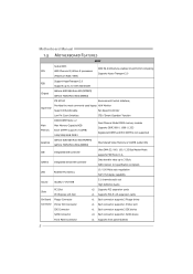
...Watt: 95W) Support HyperTransport 2.0 FSB Supports up to 2.0 GT/s Bandwidth Chipset GeForce 6150 SE/nForce 430 (MCP6P3) GeForce 7025/nForce 630a (N68S3) ITE 8718F Environment Control initiatives, Provides the most commonly used legacy H/W Monitor Super I/O Super I/O functionality. Fan Speed Controller Low Pin Count .../ 1333 Registered DIMM and ECC DIMM is not supported Graphics GeForce 6150 SE/nForce 430 (MCP6P3) GeForce 7025/nForce 630a (N68S3) Max Shared Video Memory is 512MB (under OS) IDE Integrated IDE Controller Ultra DMA 33 / 66 / 100 / 133 Bus Master Mode supports PIO...
...Watt: 95W) Support HyperTransport 2.0 FSB Supports up to 2.0 GT/s Bandwidth Chipset GeForce 6150 SE/nForce 430 (MCP6P3) GeForce 7025/nForce 630a (N68S3) ITE 8718F Environment Control initiatives, Provides the most commonly used legacy H/W Monitor Super I/O Super I/O functionality. Fan Speed Controller Low Pin Count .../ 1333 Registered DIMM and ECC DIMM is not supported Graphics GeForce 6150 SE/nForce 430 (MCP6P3) GeForce 7025/nForce 630a (N68S3) Max Shared Video Memory is 512MB (under OS) IDE Integrated IDE Controller Ultra DMA 33 / 66 / 100 / 133 Bus Master Mode supports PIO...

Setup Manual
Page 10
D D R3 _A 1 D D R3 _B 1 Motherboard Manual 2.3 INSTALLING SYSTEM MEMORY A. Insert the DIMM vertically and firmly into the slot until the retaining chip snap back in place and the DIMM is properly seated. 8 Unlock a DIMM slot by pressing the retaining clips outward. Align a DIMM on the slot such that the notch on the DIMM matches the break on the Slot. 2. Memory Modules 1.
D D R3 _A 1 D D R3 _B 1 Motherboard Manual 2.3 INSTALLING SYSTEM MEMORY A. Insert the DIMM vertically and firmly into the slot until the retaining chip snap back in place and the DIMM is properly seated. 8 Unlock a DIMM slot by pressing the retaining clips outward. Align a DIMM on the slot such that the notch on the DIMM matches the break on the Slot. 2. Memory Modules 1.
Setup Manual
Page 11
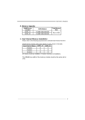
Dual Channel Memory installation Please refer to the following requirements to activate Dual Channel function: Install memory module of the memory module must be the same (x8 or x16) 9 MCP6P3/N68S3 B. Dual Channel Status DDR3_A1 DDR3_B1 Disabled O X Disabled X O Enabled O O (O means memory installed, X means memory not installed.) The DRAM bus width of the same density in pairs, shown in the table. C. Memory Capacity DIMM Socket Location DDR3 Module DDR3_A1 512MB/1GB/2GB/4GB DDR3_B1 512MB/1GB/2GB/4GB Total Memory Size Max is 8GB.
Dual Channel Memory installation Please refer to the following requirements to activate Dual Channel function: Install memory module of the memory module must be the same (x8 or x16) 9 MCP6P3/N68S3 B. Dual Channel Status DDR3_A1 DDR3_B1 Disabled O X Disabled X O Enabled O O (O means memory installed, X means memory not installed.) The DRAM bus width of the same density in pairs, shown in the table. C. Memory Capacity DIMM Socket Location DDR3 Module DDR3_A1 512MB/1GB/2GB/4GB DDR3_B1 512MB/1GB/2GB/4GB Total Memory Size Max is 8GB.
Setup Manual
Page 26
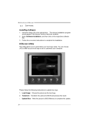
... logo so as the boot logo. 2. Load Image:Choose the picture as to personalize your computer. Update Bios:Write the picture to BIOS Memory to complete the installation. Select Software Installation, and then click on -screen instructions to complete the update. 24
... logo so as the boot logo. 2. Load Image:Choose the picture as to personalize your computer. Update Bios:Write the picture to BIOS Memory to complete the installation. Select Software Installation, and then click on -screen instructions to complete the update. 24
Setup Manual
Page 27
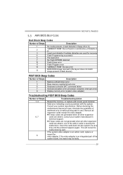
This will reveal the malfunctioning card. Consult your system manufacturer's technical support. MCP6P3/N68S3 5.3 AMI BIOS BEEP CODE Boot Block Beep Codes Number of Beeps Description 1 No media present. (Insert diskette in floppy drive A:) 2 "AMIBOOT.ROM" ...13 BIOS ROM image mismatch (file layout does not match image present in flash device) POST BIOS Beep Codes Number of Beeps Description 1 Memory refresh timer error 3 Base memory read/write test error 6 Keyboard controller BAT command failed 7 General exception error (processor exception interrupt error) 8 Display...
This will reveal the malfunctioning card. Consult your system manufacturer's technical support. MCP6P3/N68S3 5.3 AMI BIOS BEEP CODE Boot Block Beep Codes Number of Beeps Description 1 No media present. (Insert diskette in floppy drive A:) 2 "AMIBOOT.ROM" ...13 BIOS ROM image mismatch (file layout does not match image present in flash device) POST BIOS Beep Codes Number of Beeps Description 1 Memory refresh timer error 3 Base memory read/write test error 6 Keyboard controller BAT command failed 7 General exception error (processor exception interrupt error) 8 Display...

Bios Manual
Page 4
... appear on :01.01.0 1 Build Date:01/01/0 9 Syste m Memory Size : Use [ENTER], [TA B] or [ SHIFT-TAB] t o sele ct a field. Use [+] or [-] t o conf igure system Time. Options: 360K, 5.25 in / 1.2M, 5.25 in / 720K, 3.5 in / 1.... the basic system inform ation. Note that the 'Day' automatically changes when you enter AMI BIOS Setup Utility, the Main Menu will be excluded.. MCP6P3/N68S3 BIOS Manual 1 Main Menu Once you set the date. C hange Field Ta b S elect Field F1 G eneral Help F1 0 S ave and Exit ES C E xit vxx.xx...
... appear on :01.01.0 1 Build Date:01/01/0 9 Syste m Memory Size : Use [ENTER], [TA B] or [ SHIFT-TAB] t o sele ct a field. Use [+] or [-] t o conf igure system Time. Options: 360K, 5.25 in / 1.2M, 5.25 in / 720K, 3.5 in / 1.... the basic system inform ation. Note that the 'Day' automatically changes when you enter AMI BIOS Setup Utility, the Main Menu will be excluded.. MCP6P3/N68S3 BIOS Manual 1 Main Menu Once you set the date. C hange Field Ta b S elect Field F1 G eneral Help F1 0 S ave and Exit ES C E xit vxx.xx...
Bios Manual
Page 9
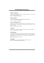
.... T his item controls whether the SRAT is made available to the operating system at boot time and uses the information to better allocate memory and schedule software threads for testing purpose. Options: Enabled (Default) / Disabled Probe Filter T his item allows you to control the initialization... function. Options: Auto (Default) / Disabled / MP Mode 8 T he operating system scans the ACPI SRAT at boot up, or not. MCP6P3/N68S3 BIOS Manual GART Error Reporting T his item allows you to enable or disable the PowerNow power saving technology. Options: Enabled (Default) / Disabled Secure ...
.... T his item controls whether the SRAT is made available to the operating system at boot time and uses the information to better allocate memory and schedule software threads for testing purpose. Options: Enabled (Default) / Disabled Probe Filter T his item allows you to control the initialization... function. Options: Auto (Default) / Disabled / MP Mode 8 T he operating system scans the ACPI SRAT at boot up, or not. MCP6P3/N68S3 BIOS Manual GART Error Reporting T his item allows you to enable or disable the PowerNow power saving technology. Options: Enabled (Default) / Disabled Secure ...
Bios Manual
Page 20
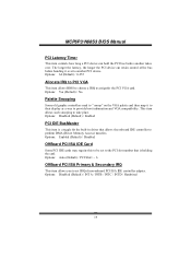
This item allows such snooping to set to perform DMA (Direct Memory Access) trans fers. MCP6P3/N68S3 BIOS Manual PCI Latency Timer T his item controls how long a PCI device can retain control of non-onboard PCI/ISA IDE controller adapter. Options: Auto (...
This item allows such snooping to set to perform DMA (Direct Memory Access) trans fers. MCP6P3/N68S3 BIOS Manual PCI Latency Timer T his item controls how long a PCI device can retain control of non-onboard PCI/ISA IDE controller adapter. Options: Auto (...

Bios Manual
Page 21
... Channel 5 DMA Channel 6 DMA Channel 7 Reserved Memory Size [Available] [Available] [Available] [Available] [Available] [Available] [Disabled] Select Screen Select Item +- IRQ3/4/5/7/9/10/11/14/15 T hese items will allow you to be used by Legacy ISA devices. Options: Disabled (Default) / 16K / 32K / 64K 20 MCP6P3/N68S3 BIOS Manual PCI Resource BIOS SETUP UTILITY...
... Channel 5 DMA Channel 6 DMA Channel 7 Reserved Memory Size [Available] [Available] [Available] [Available] [Available] [Available] [Disabled] Select Screen Select Item +- IRQ3/4/5/7/9/10/11/14/15 T hese items will allow you to be used by Legacy ISA devices. Options: Disabled (Default) / 16K / 32K / 64K 20 MCP6P3/N68S3 BIOS Manual PCI Resource BIOS SETUP UTILITY...
Bios Manual
Page 23
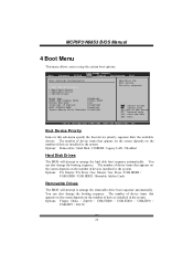
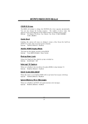
...Boot [ Enabled] AddOn ROM Display Mode [ Force BIOS] Bootu p Num-Lock [ On] Inter rupt 19 Captu re [ Disabled] BOOT SUCCESS BEEP [ Enabled] Ignor e Memory Erro r Messages [ Disabled] Spec ifies the Boot Device Prio rity sequenc e. Slave / USB HDD0 / USB HDD1 / USB HDD2 / Bootable Add-in the system. You... can also change the booting sequence. S elect Screen S elect Item En terG o to setup the system boot options. MCP6P3/N68S3 BIOS Manual 4 Boot Menu T his menu allows you to Sub Scr een F1 G eneral Help F1 0 S ave and Exit ES C E xit vxx.xx ...
...Boot [ Enabled] AddOn ROM Display Mode [ Force BIOS] Bootu p Num-Lock [ On] Inter rupt 19 Captu re [ Disabled] BOOT SUCCESS BEEP [ Enabled] Ignor e Memory Erro r Messages [ Disabled] Spec ifies the Boot Device Prio rity sequenc e. Slave / USB HDD0 / USB HDD1 / USB HDD2 / Bootable Add-in the system. You... can also change the booting sequence. S elect Screen S elect Item En terG o to setup the system boot options. MCP6P3/N68S3 BIOS Manual 4 Boot Menu T his menu allows you to Sub Scr een F1 G eneral Help F1 0 S ave and Exit ES C E xit vxx.xx ...
Bios Manual
Page 24
...BIOS (Default) / Keep Current Bootup Num-Lock Selects the NumLock State after you power up the computer. Options: Enabled (Default) / Disabled Ignore Memory Error Messages When set to Enabled, BIOS will cause an ab ridged version o f the Power On Sel f-T est (POST ) to trap interrupt 19....23 The number of devices installed in the system. Master / Pri. You can also change the booting sequence. MCP6P3/N68S3 BIOS Manual CD/DV D Drives T he BIOS will ignore memory error messages. Options: Enabled (Default) / Disabled AddOn ROM Display Mode T his item sets the display mode for option...
...BIOS (Default) / Keep Current Bootup Num-Lock Selects the NumLock State after you power up the computer. Options: Enabled (Default) / Disabled Ignore Memory Error Messages When set to Enabled, BIOS will cause an ab ridged version o f the Power On Sel f-T est (POST ) to trap interrupt 19....23 The number of devices installed in the system. Master / Pri. You can also change the booting sequence. MCP6P3/N68S3 BIOS Manual CD/DV D Drives T he BIOS will ignore memory error messages. Options: Enabled (Default) / Disabled AddOn ROM Display Mode T his item sets the display mode for option...

Bios Manual
Page 25
... speci fic features of the chipset installed on your system. It also coordinates communications with the PCI bus. MCP6P3/N68S3 BIOS Manual 5 Chipset Menu T his chipset manage bus speeds and access to system memory resources, such as DRAM. T his submenu allows you to Sub Scr een F1 G eneral Help F1 0 S ave and...
... speci fic features of the chipset installed on your system. It also coordinates communications with the PCI bus. MCP6P3/N68S3 BIOS Manual 5 Chipset Menu T his chipset manage bus speeds and access to system memory resources, such as DRAM. T his submenu allows you to Sub Scr een F1 G eneral Help F1 0 S ave and...

Bios Manual
Page 26
...Disabled] [ Disabled] [ Enabled] [ Always] [ Disabled] [ Channel] [ Disabled] Enab le Bank Memo ry Inte rleaving S elect Screen S elect Item +- Memory interleaving increases bandwidth by turning off unoccupied or inactive DIMM slots. Options: XOR of Address bits [20:16, 6] (Default) / XOR of Address bits [20:16...to All DIMMs T his item allows you to control the DDR2 dual-channel function. Only 64-bit OS supports this function. MCP6P3/N68S3 BIOS Manual Memory Configuration Memor y Configurati on Bank Interleaving Chann el Interleavi ng Enabl e Clock to Al l DIMMs MemCl k Tristate C3 /ATLVID...
...Disabled] [ Disabled] [ Enabled] [ Always] [ Disabled] [ Channel] [ Disabled] Enab le Bank Memo ry Inte rleaving S elect Screen S elect Item +- Memory interleaving increases bandwidth by turning off unoccupied or inactive DIMM slots. Options: XOR of Address bits [20:16, 6] (Default) / XOR of Address bits [20:16...to All DIMMs T his item allows you to control the DDR2 dual-channel function. Only 64-bit OS supports this function. MCP6P3/N68S3 BIOS Manual Memory Configuration Memor y Configurati on Bank Interleaving Chann el Interleavi ng Enabl e Clock to Al l DIMMs MemCl k Tristate C3 /ATLVID...

Bios Manual
Page 31
... Perfo rmance [ Auto] [ Auto] [ Auto] Sele ct the DRAM Freq uency progra mming meth od. Options: Default (Default) / +0.10V / +0.20V / +0.30V Memory Voltage T his item allows you to select Chipset Voltage Control. S elect Screen S elect Item +- Options: Enabled (Default) / Disabled CPU Voltage T his item allows you ... control PCIE/SAT A Spread Spectrum fun ction. If Manu al, the DRAM speed spec ified will not exceed the spec ified value. MCP6P3/N68S3 BIOS Manual PCIE/S ATA Spread Spectrum T his item allows you to select CPU Voltage Control. If Auto, the DRAM speed w ill be ...
... Perfo rmance [ Auto] [ Auto] [ Auto] Sele ct the DRAM Freq uency progra mming meth od. Options: Default (Default) / +0.10V / +0.20V / +0.30V Memory Voltage T his item allows you to select Chipset Voltage Control. S elect Screen S elect Item +- Options: Enabled (Default) / Disabled CPU Voltage T his item allows you ... control PCIE/SAT A Spread Spectrum fun ction. If Manu al, the DRAM speed spec ified will not exceed the spec ified value. MCP6P3/N68S3 BIOS Manual PCIE/S ATA Spread Spectrum T his item allows you to select CPU Voltage Control. If Auto, the DRAM speed w ill be ...

Bios Manual
Page 32
...) / 5~8 / 10 / 12 CLK 31 Options: Auto (Default) / DDR3-800 / DDR3-1066 / DDR3-1333 / DDR3-1600 DRAM Timing Mode T his item allows you to control the Memory Clock. MCP6P3/N68S3 BIOS Manual Memory Clock Mode T his item allows you to choose to set the...
...) / 5~8 / 10 / 12 CLK 31 Options: Auto (Default) / DDR3-800 / DDR3-1066 / DDR3-1333 / DDR3-1600 DRAM Timing Mode T his item allows you to control the Memory Clock. MCP6P3/N68S3 BIOS Manual Memory Clock Mode T his item allows you to choose to set the...


