Setup Manual
Page 1
... in writing. There is not allowed without first obtaining the vendor's approval in whole, is no representations or warranties with respect to notify any purpose. MCP6PB M2+ Setup Manual FCC Information and Copyright This equipment has been tested and found in a particular installation. Duplication of this user's manual is subject to be...
... in writing. There is not allowed without first obtaining the vendor's approval in whole, is no representations or warranties with respect to notify any purpose. MCP6PB M2+ Setup Manual FCC Information and Copyright This equipment has been tested and found in a particular installation. Duplication of this user's manual is subject to be...
Setup Manual
Page 3
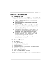
... dangerous area, such as heat source, humid air and water. 1.2 PACKAGE CHECKLIST IDE Cable X 1 Serial ATA Cable X 1 Rear I/O Panel for choosing our product. CHAPTER 1: INTRODUCTION MCP6PB M2+ 1.1 BEFORE YOU START Thank you take the motherboard out from anti-static bag, ground yourself properly by area or your motherboard version. 1 Hold the board...
... dangerous area, such as heat source, humid air and water. 1.2 PACKAGE CHECKLIST IDE Cable X 1 Serial ATA Cable X 1 Rear I/O Panel for choosing our product. CHAPTER 1: INTRODUCTION MCP6PB M2+ 1.1 BEFORE YOU START Thank you take the motherboard out from anti-static bag, ground yourself properly by area or your motherboard version. 1 Hold the board...
Setup Manual
Page 5
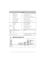
... VGA port I/O LAN port USB Port Audio Jack Board Size 170 mm(W) x 235 mm(L) Special Features RAID 0 / 1 OS Support Windows XP / Vista / 7 MCP6PB M2+ SPEC x1 CPU Fan power supply (with Smart Fan function) x1 System Fan Power supply x1 Restore CMOS data to factory default x2 Each connector... Connect to D-SUB monitor x1 Connect to RJ-45 ethernet cable x4 Connect to USB devices x3 Provide Audio-In/Out and microphone connection MicroATX Biostar Reserves the right to add or remove support for any OS With or without notice. 1.4 REAR PANEL CONNECTORS PS/2 Mouse PS/ 2 Key ...
... VGA port I/O LAN port USB Port Audio Jack Board Size 170 mm(W) x 235 mm(L) Special Features RAID 0 / 1 OS Support Windows XP / Vista / 7 MCP6PB M2+ SPEC x1 CPU Fan power supply (with Smart Fan function) x1 System Fan Power supply x1 Restore CMOS data to factory default x2 Each connector... Connect to D-SUB monitor x1 Connect to RJ-45 ethernet cable x4 Connect to USB devices x3 Provide Audio-In/Out and microphone connection MicroATX Biostar Reserves the right to add or remove support for any OS With or without notice. 1.4 REAR PANEL CONNECTORS PS/2 Mouse PS/ 2 Key ...
Setup Manual
Page 7
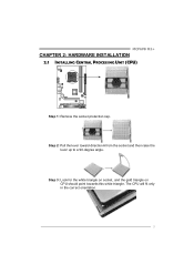
The CPU will fit only in the correct orientation. 5 MCP6PB M2+ CHAPTER 2: HARDWARE INSTALLATION 2.1 INSTALLING CENTRAL PROCESSING UNIT (CPU) Step 1: Remove the socket protection cap. Step 3: Look for the white triangle on socket, and the gold triangle on CPU should point towards this white triangle. Step 2: Pull the lever toward direction A from the socket and then raise the lever up to a 90-degree angle.
The CPU will fit only in the correct orientation. 5 MCP6PB M2+ CHAPTER 2: HARDWARE INSTALLATION 2.1 INSTALLING CENTRAL PROCESSING UNIT (CPU) Step 1: Remove the socket protection cap. Step 3: Look for the white triangle on socket, and the gold triangle on CPU should point towards this white triangle. Step 2: Pull the lever toward direction A from the socket and then raise the lever up to a 90-degree angle.
Setup Manual
Page 9
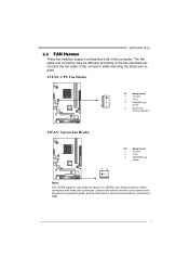
... RPM rate sense Note: The JCFAN supports 4-pin head connector; the JSFAN, 3-pin head connector. The fan cable and connector may be connected to pin#1. MCP6PB M2+ 2.2 FAN HEADERS These fan headers support cooling-fans built in the computer.
... RPM rate sense Note: The JCFAN supports 4-pin head connector; the JSFAN, 3-pin head connector. The fan cable and connector may be connected to pin#1. MCP6PB M2+ 2.2 FAN HEADERS These fan headers support cooling-fans built in the computer.
Setup Manual
Page 11
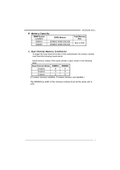
... the memory module must meet the following table. Memory Capacity DIMM Socket Location DDR2 Module DIMMA1 256MB/512MB/1GB/2GB DIMMB1 256MB/512MB/1GB/2GB MCP6PB M2+ Total Memory Size Max is 4GB.
... the memory module must meet the following table. Memory Capacity DIMM Socket Location DDR2 Module DIMMA1 256MB/512MB/1GB/2GB DIMMB1 256MB/512MB/1GB/2GB MCP6PB M2+ Total Memory Size Max is 4GB.
Setup Manual
Page 13
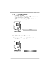
MCP6PB M2+ PEX16_1: PCI-Express Gen2 x16 Slot - PCI-Express supports a raw bit-rate of 8GB/s totally. - PCI stands for Peripheral Component Interconnect, and it is equipped with 1 standard PCI slot. PCI1 11 Maximum theoretical realized bandwidth of 4GB/s simultaneously per direction, for expansion cards. PEX16_1 PCI1: Peripheral Component Interconnect Slot This motherboard is a bus standard for an aggregate of 2.5Gb/s on the data pins. - 2X bandwidth over the traditional PCI architecture. This PCI slot is designated as 32 bits. PCI-Express 1.0a compliant. -
MCP6PB M2+ PEX16_1: PCI-Express Gen2 x16 Slot - PCI-Express supports a raw bit-rate of 8GB/s totally. - PCI stands for Peripheral Component Interconnect, and it is equipped with 1 standard PCI slot. PCI1 11 Maximum theoretical realized bandwidth of 4GB/s simultaneously per direction, for expansion cards. PEX16_1 PCI1: Peripheral Component Interconnect Slot This motherboard is a bus standard for an aggregate of 2.5Gb/s on the data pins. - 2X bandwidth over the traditional PCI architecture. This PCI slot is designated as 32 bits. PCI-Express 1.0a compliant. -
Setup Manual
Page 15
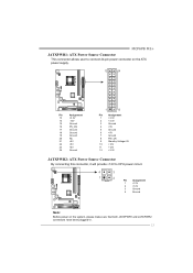
MCP6PB M2+ JATXPWR1: ATX Power Source Connector This connector allows user to connect 24-pin power connector on the ATX power supply. 12 24 Pin Assignment 13 +3....
MCP6PB M2+ JATXPWR1: ATX Power Source Connector This connector allows user to connect 24-pin power connector on the ATX power supply. 12 24 Pin Assignment 13 +3....
Setup Manual
Page 17
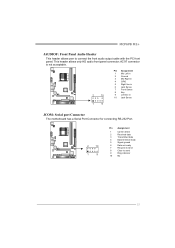
... data 4 Data terminal ready 5 Signal ground 6 Data set ready 7 Request to send 8 Clear to connect the front audio output cable with the PC front panel. MCP6PB M2+ JAUDIOF: Front Panel Audio Header This header allows user to send 9 Ring indicator 10 NC 15
... data 4 Data terminal ready 5 Signal ground 6 Data set ready 7 Request to send 8 Clear to connect the front audio output cable with the PC front panel. MCP6PB M2+ JAUDIOF: Front Panel Audio Header This header allows user to send 9 Ring indicator 10 NC 15
Setup Manual
Page 19
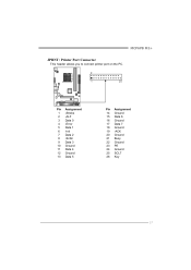
MCP6PB M2+ JPRNT: Printer Port Connector This header allows you to connect printer port on the PC. 2 1 25 Pin Assignment 1 -Strobe 2 -ALF 3 Data 0 4 -Error 5 Data 1 6 -Init 7 Data 2 8 -Scltin 9 Data 3 10 Ground 11 Data 4 12 Ground 13 Data 5 Pin Assignment 14 Ground 15 Data 6 16 Ground 17 Data 7 18 Ground 19 -ACK 20 Ground 21 Busy 22 Ground 23 PE 24 Ground 25 SCLT 26 Key 17
MCP6PB M2+ JPRNT: Printer Port Connector This header allows you to connect printer port on the PC. 2 1 25 Pin Assignment 1 -Strobe 2 -ALF 3 Data 0 4 -Error 5 Data 1 6 -Init 7 Data 2 8 -Scltin 9 Data 3 10 Ground 11 Data 4 12 Ground 13 Data 5 Pin Assignment 14 Ground 15 Data 6 16 Ground 17 Data 7 18 Ground 19 -ACK 20 Ground 21 Busy 22 Ground 23 PE 24 Ground 25 SCLT 26 Key 17
Setup Manual
Page 21
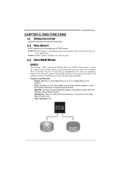
Block 1 Block 3 Block 5 Block 2 Block 4 Block 6 19 It breaks up to 6 or 8. Depending on the system environment. MCP6PB M2+ CHAPTER 4: RAID FUNCTIONS 4.1 OPERATING SYSTEM Supports Windows XP and Windows Vista. 4.2 RAID ARRAYS RAID supports the following types of the RAID set during the creation ...
Block 1 Block 3 Block 5 Block 2 Block 4 Block 6 19 It breaks up to 6 or 8. Depending on the system environment. MCP6PB M2+ CHAPTER 4: RAID FUNCTIONS 4.1 OPERATING SYSTEM Supports Windows XP and Windows Vista. 4.2 RAID ARRAYS RAID supports the following types of the RAID set during the creation ...
Setup Manual
Page 23
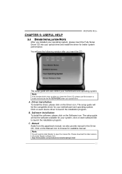
CHAPTER 5: USEFUL HELP MCP6PB M2+ 5.1 DRIVER INSTALLATION NOTE After you installed your operating system, please insert the Fully Setup Driver CD into your optical drive. Click on each software title ...
CHAPTER 5: USEFUL HELP MCP6PB M2+ 5.1 DRIVER INSTALLATION NOTE After you installed your operating system, please insert the Fully Setup Driver CD into your optical drive. Click on each software title ...
Setup Manual
Page 25
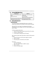
... the CPU, and the system may not power on the system again. 23 CPU fan is placed evenly with the CPU speed. Wait for seconds. 2. MCP6PB M2+ 5.3 AWARD BIOS BEEP CODE Beep Sound Meaning One long beep followed by two short Video card not found during POST Long beeps every other second...
... the CPU, and the system may not power on the system again. 23 CPU fan is placed evenly with the CPU speed. Wait for seconds. 2. MCP6PB M2+ 5.3 AWARD BIOS BEEP CODE Beep Sound Meaning One long beep followed by two short Video card not found during POST Long beeps every other second...

Setup Manual
Page 27
MCP6PB M2+ This page is intentionally left blank. 25
MCP6PB M2+ This page is intentionally left blank. 25
Bios Manual
Page 1
MCP6PB M2+ BIOS Setup Table of Contents BIOS Setup 2 1 Main Menu 4 2 Standard CMOS Features 7 3 Advanced BIOS Features 9 4 Advanced Chipset Features 15 5 Integrated Peripherals 18 6 Power Management Setup 25 7 PnP/PCI Configurations 29 8 PC Health Status 32 9 Performance Booster Zone 35 1
MCP6PB M2+ BIOS Setup Table of Contents BIOS Setup 2 1 Main Menu 4 2 Standard CMOS Features 7 3 Advanced BIOS Features 9 4 Advanced Chipset Features 15 5 Integrated Peripherals 18 6 Power Management Setup 25 7 PnP/PCI Configurations 29 8 PC Health Status 32 9 Performance Booster Zone 35 1
Bios Manual
Page 2
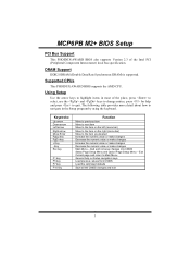
... the ACPI specification, developed by Microsoft, Intel and Toshiba. 2 APM Support This PHOENIX-AWARD BIOS supports Version 1.1&1.2 of Advanced Configuration and Power interface specification (ACPI). MCP6PB M2+ BIOS Setup BIOS Setup Introduction The purpose of this manual is turned off. The power of the booting process, loading and executing the operating system...
... the ACPI specification, developed by Microsoft, Intel and Toshiba. 2 APM Support This PHOENIX-AWARD BIOS supports Version 1.1&1.2 of Advanced Configuration and Power interface specification (ACPI). MCP6PB M2+ BIOS Setup BIOS Setup Introduction The purpose of this manual is turned off. The power of the booting process, loading and executing the operating system...
Bios Manual
Page 3
... Use the arrow keys to highlight items in the Setup program by using the keyboard. The following table provides more detail about how to quit. MCP6PB M2+ BIOS Setup PCI Bus Support This PHOENIX-AWARD BIOS also supports Version 2.3 of the place, press to select, use the and keys to change entries...
... Use the arrow keys to highlight items in the Setup program by using the keyboard. The following table provides more detail about how to quit. MCP6PB M2+ BIOS Setup PCI Bus Support This PHOENIX-AWARD BIOS also supports Version 2.3 of the place, press to select, use the and keys to change entries...
Bios Manual
Page 4
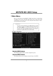
For better system performance, the BIOS firmware is for your reference only. MCP6PB M2+ BIOS Setup 1 Main Menu Once you to configure advanced features of the BIOS. 4 WARNING !! Advanced BIOS Features This submenu allows you enter Phoenix-Award BIOS&#...
For better system performance, the BIOS firmware is for your reference only. MCP6PB M2+ BIOS Setup 1 Main Menu Once you to configure advanced features of the BIOS. 4 WARNING !! Advanced BIOS Features This submenu allows you enter Phoenix-Award BIOS&#...
Bios Manual
Page 5
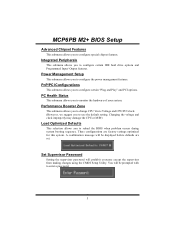
Integrated Peripherals This submenu allows you to configure special chipset features. MCP6PB M2+ BIOS Setup Advanced Chipset Features This submenu allows you to configure certain IDE hard drive options and Programmed Input/ Output features. Performance Booster Zone This ...
Integrated Peripherals This submenu allows you to configure special chipset features. MCP6PB M2+ BIOS Setup Advanced Chipset Features This submenu allows you to configure certain IDE hard drive options and Programmed Input/ Output features. Performance Booster Zone This ...
Bios Manual
Page 6
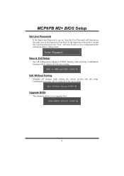
MCP6PB M2+ BIOS Setup Set User Password If the Supervisor Password is set , then the User Password will function in the same way as the Supervisor Password. ...
MCP6PB M2+ BIOS Setup Set User Password If the Supervisor Password is set , then the User Password will function in the same way as the Supervisor Password. ...


