
M6VCG user's manual
Page 14
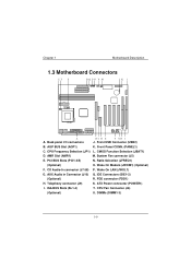
... (J9) S. Wake On Modem (JWOM1) (Optional) F. DIMMs (DIMM1-3) Back panel I . AMR Slot (AMR1) M. IDE Connectors (IDE1-2) (Optional) R. Front Panel CONN. (PANEL1) C. System Fan connector (J5) E. ATX Power connector (POWER1) I /O connectors J.
... (J9) S. Wake On Modem (JWOM1) (Optional) F. DIMMs (DIMM1-3) Back panel I . AMR Slot (AMR1) M. IDE Connectors (IDE1-2) (Optional) R. Front Panel CONN. (PANEL1) C. System Fan connector (J5) E. ATX Power connector (POWER1) I /O connectors J.
M6VCG user's manual
Page 15
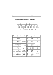
Chapter 1 Motherboard Description 1.3.1 Front Panel Connectors : PANEL1 NC Pin Assignment Function No. 1 Speaker 2 NC Speaker 3 Ground Connector 4 +5V 5 Power LED(+) 6 NC Power LED 7 Ground 8 NC No 9 NC Function 10 Power Switch ATX Power 11 Ground Button 12 Reset Switch Reset 13 Ground Button Pin Assignment No. 14 +5V 15 Ground 16 NC 17 Sleep Switch 18 Ground 19 NC 20 HDD LED(-) 21 HDD LED(+) 22 +5V 23 NC 24 IRRX 25 Ground 26 IRTX Function VCC Ground NC SMI NC HDD LED IrDA Connector
Chapter 1 Motherboard Description 1.3.1 Front Panel Connectors : PANEL1 NC Pin Assignment Function No. 1 Speaker 2 NC Speaker 3 Ground Connector 4 +5V 5 Power LED(+) 6 NC Power LED 7 Ground 8 NC No 9 NC Function 10 Power Switch ATX Power 11 Ground Button 12 Reset Switch Reset 13 Ground Button Pin Assignment No. 14 +5V 15 Ground 16 NC 17 Sleep Switch 18 Ground 19 NC 20 HDD LED(-) 21 HDD LED(+) 22 +5V 23 NC 24 IRRX 25 Ground 26 IRTX Function VCC Ground NC SMI NC HDD LED IrDA Connector
M6VCG user's manual
Page 19
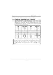
Chapter 1 Motherboard Description 1.3.2 ATX 20-pin Power Connector : POWER1 PIN VOLTAGE PIN VOLTAGE 1 3.3 V 11 3.3 V 2 3.3 V 12 -12 V 3 GND 13 GND 4 5 V 14 PS_ON 5 GND 15 GND 6 5 V 16 GND 7 GND 17 GND 8 PW_OK 18 -5 V (Optional) 9 5V_SB 19 5 V 10 12 V 20 5 V Warning: Since the motherboard has the instant power on function, make sure that all components are installed properly before inserting the power connector to ensure that no damage will be done.
Chapter 1 Motherboard Description 1.3.2 ATX 20-pin Power Connector : POWER1 PIN VOLTAGE PIN VOLTAGE 1 3.3 V 11 3.3 V 2 3.3 V 12 -12 V 3 GND 13 GND 4 5 V 14 PS_ON 5 GND 15 GND 6 5 V 16 GND 7 GND 17 GND 8 PW_OK 18 -5 V (Optional) 9 5V_SB 19 5 V 10 12 V 20 5 V Warning: Since the motherboard has the instant power on function, make sure that all components are installed properly before inserting the power connector to ensure that no damage will be done.