Setup Manual
Page 2
... 1: Introduction 1 1.1 Before You Start 1 1.2 Package Checklist 1 1.3 Motherboard Features 2 1.4 Rear Panel Connectors 4 1.5 Motherboard Layout 5 Chapter 2: Hardware Installation 6 2.1 Installing Central Processing Unit (CPU 6 2.2 FAN Headers 8 2.3 Installing System Memory 9 2.4 Connectors and Slots 11 Chapter 3: Headers & Jumpers Setup 14 3.1 How to Setup Jumpers 14 3.2 Detail Settings 14 Chapter 4: RAID Functions 19 4.1 Operating System 19 4.2 Raid...
... 1: Introduction 1 1.1 Before You Start 1 1.2 Package Checklist 1 1.3 Motherboard Features 2 1.4 Rear Panel Connectors 4 1.5 Motherboard Layout 5 Chapter 2: Hardware Installation 6 2.1 Installing Central Processing Unit (CPU 6 2.2 FAN Headers 8 2.3 Installing System Memory 9 2.4 Connectors and Slots 11 Chapter 3: Headers & Jumpers Setup 14 3.1 How to Setup Jumpers 14 3.2 Detail Settings 14 Chapter 4: RAID Functions 19 4.1 Operating System 19 4.2 Raid...
Setup Manual
Page 4
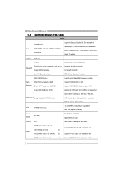
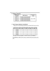
... Fan Speed Controller Low Pin Count Interface ITE's "Smart Guardian" function DDR3 DIMM Slots x 4 Dual Channel Mode DDR3 memory module Main Memory Max Memory Capacity 32GB Each DIMM supports 512MB/ Supports DDR3 1066 / 1333 Supports DDR3 1600 (depending on CPU) x1 PCI Express Gen2...Socket 1155 SpeedStep® / Intel Architecture-64 / Extended CPU Intel Core i7 / i5 / i3 / Pentium / Celeron Memory 64 Technology / Virtualization Technology / processor Hyper Threading Chipset Intel H77 IT8728 Environment Control initiatives, Super I/O Provides the most commonly used legacy ...
... Fan Speed Controller Low Pin Count Interface ITE's "Smart Guardian" function DDR3 DIMM Slots x 4 Dual Channel Mode DDR3 memory module Main Memory Max Memory Capacity 32GB Each DIMM supports 512MB/ Supports DDR3 1066 / 1333 Supports DDR3 1600 (depending on CPU) x1 PCI Express Gen2...Socket 1155 SpeedStep® / Intel Architecture-64 / Extended CPU Intel Core i7 / i5 / i3 / Pentium / Celeron Memory 64 Technology / Virtualization Technology / processor Hyper Threading Chipset Intel H77 IT8728 Environment Control initiatives, Super I/O Provides the most commonly used legacy ...
Setup Manual
Page 11
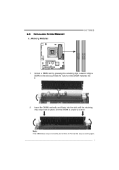
Unlock a DIMM slot by pressing the retaining clips outward. Align a DIMM on the slot such that the notch on the DIMM matches the break on the Slot. 2. Memory Modules H77MU3 D DR3_A1 DD R3_A2 DD R3_B1 DD R3_B2 1. Note: If the DIMM does not go in place and the DIMM is properly seated. Insert the DIMM vertically and firmly into the slot until the retaining chip snap back in smoothly, do not force it all the way out and try again. 9 Pull it . 2.3 INSTALLING SYSTEM MEMORY A.
Unlock a DIMM slot by pressing the retaining clips outward. Align a DIMM on the slot such that the notch on the DIMM matches the break on the Slot. 2. Memory Modules H77MU3 D DR3_A1 DD R3_A2 DD R3_B1 DD R3_B2 1. Note: If the DIMM does not go in place and the DIMM is properly seated. Insert the DIMM vertically and firmly into the slot until the retaining chip snap back in smoothly, do not force it all the way out and try again. 9 Pull it . 2.3 INSTALLING SYSTEM MEMORY A.
Setup Manual
Page 12
... Please refer to the following requirements to activate Dual Channel function: Install memory module of the memory module must be the same (x8 or x16) 10 Memory Capacity DIMM Socket Location DDR3 Module DDR3_A1 512MB/1GB/2GB/4GB/8GB DDR3_A2 512MB.../4GB/8GB DDR3_B2 512MB/1GB/2GB/4GB/8GB Total Memory Size Max is 32GB. Motherboard Manual B. Dual Channel Status DDR3_A1 DDR3_A2 DDR3_B1 DDR3_B2 Enabled O X O X Enabled X O X O Enabled O O O O Enabled O X X O Enabled X O O X (O means memory installed, X means memory not installed.) The DRAM bus width of the same...
... Please refer to the following requirements to activate Dual Channel function: Install memory module of the memory module must be the same (x8 or x16) 10 Memory Capacity DIMM Socket Location DDR3 Module DDR3_A1 512MB/1GB/2GB/4GB/8GB DDR3_A2 512MB.../4GB/8GB DDR3_B2 512MB/1GB/2GB/4GB/8GB Total Memory Size Max is 32GB. Motherboard Manual B. Dual Channel Status DDR3_A1 DDR3_A2 DDR3_B1 DDR3_B2 Enabled O X O X Enabled X O X O Enabled O O O O Enabled O X X O Enabled X O O X (O means memory installed, X means memory not installed.) The DRAM bus width of the same...
Setup Manual
Page 31
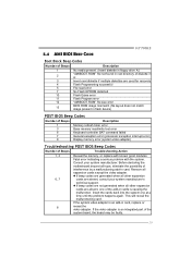
...is causing the malfunction. If the video adapter is an add-in card, replace or 8 reseat the video adapter. 5.4 AMI BIOS BEEP CODE H77MU3 Boot Block Beep Codes Number of Beeps Description 1 No media present. (Insert diskette in floppy drive A:) 2 "AMIBOOT.ROM" file not found... (file layout does not match image present in flash device) POST BIOS Beep Codes Number of Beeps Description 1 Memory refresh timer error 3 Base memory read/write test error 6 Keyboard controller BAT command failed 7 General exception error (processor exception interrupt error) 8 Display...
...is causing the malfunction. If the video adapter is an add-in card, replace or 8 reseat the video adapter. 5.4 AMI BIOS BEEP CODE H77MU3 Boot Block Beep Codes Number of Beeps Description 1 No media present. (Insert diskette in floppy drive A:) 2 "AMIBOOT.ROM" file not found... (file layout does not match image present in flash device) POST BIOS Beep Codes Number of Beeps Description 1 Memory refresh timer error 3 Base memory read/write test error 6 Keyboard controller BAT command failed 7 General exception error (processor exception interrupt error) 8 Display...
Setup Manual
Page 50
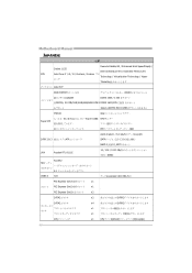
Motherboard Manual JAPANESE 仕様 Execute Disable Bit / Enhanced Intel SpeedStep® / Socket 1155 Intel Architecture-64 / Extended Memory 64 CPU Intel Core i7 / i5 / i3 / Pentium / Celeron プロ Technology / Virtualization Technology / Hyper セッサ Threading Intel H77 DDR3 DIMM x 4 DDR3 32GB ...
Motherboard Manual JAPANESE 仕様 Execute Disable Bit / Enhanced Intel SpeedStep® / Socket 1155 Intel Architecture-64 / Extended Memory 64 CPU Intel Core i7 / i5 / i3 / Pentium / Celeron プロ Technology / Virtualization Technology / Hyper セッサ Threading Intel H77 DDR3 DIMM x 4 DDR3 32GB ...
Bios Manual
Page 4
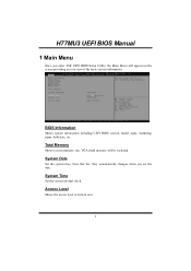
System Time Set the system internal clock. H77MU3 UEFI BIOS Manual 1 Main Menu Once you set the date. Access Level Shows the access level of the basic system information. BIOS Information Shows system information including UEFI BIOS version, model name, marketing name, built date, etc. Total Memory Shows system memory size, VGA shard memory will appear on the screen providing an overview of current user. 3 System Date Set the system date. Note that the 'Day' automatically changes when you enter AMI UEFI BIOS Setup Utility, the Main Menu will be excluded.
System Time Set the system internal clock. H77MU3 UEFI BIOS Manual 1 Main Menu Once you set the date. Access Level Shows the access level of the basic system information. BIOS Information Shows system information including UEFI BIOS version, model name, marketing name, built date, etc. Total Memory Shows system memory size, VGA shard memory will appear on the screen providing an overview of current user. 3 System Date Set the system date. Note that the 'Day' automatically changes when you enter AMI UEFI BIOS Setup Utility, the Main Menu will be excluded.
Bios Manual
Page 11
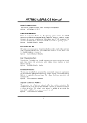
...Limit CPUID Maximum When the computer is booted up, the operating system executes the CPUID instruction to be required in each processor package. H77MU3 UEFI BIOS Manual Active Processor Cores This item sets number of basic information CPUID can provide the operating system. Options: Disabled (Default) ... cache line prefetch mechanism that are likely to identify the processor and its requirements and prefetches data and instructions from the memory into several parts, thus enhance the performance when running virtual machines or multi interface systems. Options: Disabled (Default) /...
...Limit CPUID Maximum When the computer is booted up, the operating system executes the CPUID instruction to be required in each processor package. H77MU3 UEFI BIOS Manual Active Processor Cores This item sets number of basic information CPUID can provide the operating system. Options: Disabled (Default) ... cache line prefetch mechanism that are likely to identify the processor and its requirements and prefetches data and instructions from the memory into several parts, thus enhance the performance when running virtual machines or multi interface systems. Options: Disabled (Default) /...

Bios Manual
Page 15
Options: Disabled (Default) / Enabled Active Memory Threshold This item allows system to try to support RST when partition size > Active Page Threshold size in AUTO mode and check if partition size is enough at S3 entry. Options: Disabled (Default) / Enabled 14 H77MU3 UEFI BIOS Manual Active Page Threshold Support This item allows system to zero, the item will be in MB. When set to support RST with small partition. Options: 0 (Default) PCH-FW Configuration MDES BIOS Status Code This item enables/disables MDES BIOS status code..
Options: Disabled (Default) / Enabled Active Memory Threshold This item allows system to try to support RST when partition size > Active Page Threshold size in AUTO mode and check if partition size is enough at S3 entry. Options: Disabled (Default) / Enabled 14 H77MU3 UEFI BIOS Manual Active Page Threshold Support This item allows system to zero, the item will be in MB. When set to support RST with small partition. Options: 0 (Default) PCH-FW Configuration MDES BIOS Status Code This item enables/disables MDES BIOS status code..
Bios Manual
Page 28
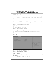
...160M / 192M / 224M / 256M / 288M / 320M / 352M / 384M / 416M / 448M / 480M / 512M / 1024M DVMT Total Gfx Mem This item select DVMT5.0 Total Graphic Memory size used by the Internal Graphics Devic e. Options: L0sL1 (Default) / Disabled / L0S / L1 27 Options: 256MB (Default) / 128MB / MAX Gfx Low Power Mode This option... DMI Link ASPM Control This item enables/ disables the control of active state power management on SA side of the DMI link.. H77MU3 UEFI BIOS Manual DVMT Pre-Allocated This item select DVMT 5.0 Pre-Allocated (Fixed) Graphics Memory size used by the Internal Graphics Device.
...160M / 192M / 224M / 256M / 288M / 320M / 352M / 384M / 416M / 448M / 480M / 512M / 1024M DVMT Total Gfx Mem This item select DVMT5.0 Total Graphic Memory size used by the Internal Graphics Devic e. Options: L0sL1 (Default) / Disabled / L0S / L1 27 Options: 256MB (Default) / 128MB / MAX Gfx Low Power Mode This option... DMI Link ASPM Control This item enables/ disables the control of active state power management on SA side of the DMI link.. H77MU3 UEFI BIOS Manual DVMT Pre-Allocated This item select DVMT 5.0 Pre-Allocated (Fixed) Graphics Memory size used by the Internal Graphics Device.
Bios Manual
Page 30
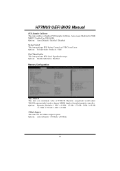
H77MU3 UEFI BIOS Manual PEG Sampler Calibrate This item enables or disables PEG Sampler Calibrate. Auto means Disabled for SNB MB/DT, Enabled for NMode support option. Options: Auto (Default) / Enabled / Disabled Swing Control This item performs PEG Swing Control, on largest MMIO length of TOLUD. Options: Enabled (Default) / Disabled Memory Configuration Max...
H77MU3 UEFI BIOS Manual PEG Sampler Calibrate This item enables or disables PEG Sampler Calibrate. Auto means Disabled for SNB MB/DT, Enabled for NMode support option. Options: Auto (Default) / Enabled / Disabled Swing Control This item performs PEG Swing Control, on largest MMIO length of TOLUD. Options: Enabled (Default) / Disabled Memory Configuration Max...
Bios Manual
Page 31
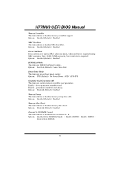
... channel A / B. Enable - Options: PPD (Default) / No Power Down / APD / APD-PPD Scrambler Seed Generation Off This item sets control memory scrambler seed generation. H77MU3 UEFI BIOS Manual Memory Scrambler This item enables or disables memory scrambler support. Options: Enabled (Default) / Disabled Force Cold Reset Force cold reset or choose MRC cold reset mode, when...
... channel A / B. Enable - Options: PPD (Default) / No Power Down / APD / APD-PPD Scrambler Seed Generation Off This item sets control memory scrambler seed generation. H77MU3 UEFI BIOS Manual Memory Scrambler This item enables or disables memory scrambler support. Options: Enabled (Default) / Disabled Force Cold Reset Force cold reset or choose MRC cold reset mode, when...
Bios Manual
Page 39
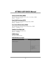
Options: 24 (Default) DRAM Voltage This item sets DRAM Voltage. H77MU3 UEFI BIOS Manual Active to Active Delay (tRRD) This item allows you to select Four Active Window Delay of DDR3. Options: 5 (Default) / 4 ~ 15 Four Active Window Delay (tFAW) This item allows you to select Row Active to Precharge Delay of DDR3. Options: 20 (Default) / 4 ~ 63 Graphics Core Ratio Limit This item sets Graphics Core Ratio Limit. BIOSTAR Memory Insight 38 Options: 4 (Default) / 4 ~ 15 Read CAS# Precharge (tRTP) This item allows you to select Read to Row Active Delay of DDR3.
Options: 24 (Default) DRAM Voltage This item sets DRAM Voltage. H77MU3 UEFI BIOS Manual Active to Active Delay (tRRD) This item allows you to select Four Active Window Delay of DDR3. Options: 5 (Default) / 4 ~ 15 Four Active Window Delay (tFAW) This item allows you to select Row Active to Precharge Delay of DDR3. Options: 20 (Default) / 4 ~ 63 Graphics Core Ratio Limit This item sets Graphics Core Ratio Limit. BIOSTAR Memory Insight 38 Options: 4 (Default) / 4 ~ 15 Read CAS# Precharge (tRTP) This item allows you to select Read to Row Active Delay of DDR3.
Bios Manual
Page 40
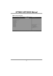
H77MU3 UEFI BIOS Manual DDR3 1/2/3/4 Information These items display SPD information of DDR3 memory. 39
H77MU3 UEFI BIOS Manual DDR3 1/2/3/4 Information These items display SPD information of DDR3 memory. 39


