Bios Setup
Page 2
...options and settings in BIOS Setup. Plug and Play Support This PHOENIX-AWARD BIOS supports the Plug and Play Version 1.0A spec ification. GF7100P-M7S BIOS Setup Introduction The purpose of CMOS RAM is supplied by this manual will to the hard disk drives and video monitors can do ...such as virus and password protection or chipset fine-tuning options are also included in the Phoenix-Award™ BIOS Setup program on this motherboard. The Setup program allows users to modify the basic system configuration and save these settings to describe the settings in BIOS. This system ...
...options and settings in BIOS Setup. Plug and Play Support This PHOENIX-AWARD BIOS supports the Plug and Play Version 1.0A spec ification. GF7100P-M7S BIOS Setup Introduction The purpose of CMOS RAM is supplied by this manual will to the hard disk drives and video monitors can do ...such as virus and password protection or chipset fine-tuning options are also included in the Phoenix-Award™ BIOS Setup program on this motherboard. The Setup program allows users to modify the basic system configuration and save these settings to describe the settings in BIOS. This system ...
Bios Setup
Page 22
... two IDE channels. As well, your system software both support Ultra DMA, select Auto to enable or disable the IDE DMA transfer access. GF7100P-M7S On-chip IDE Channel 0 The motherboard chipset contains a PCI IDE interface with support for each of the IDE devices that the onboard IDE interface supports. The Choices: Auto...
... two IDE channels. As well, your system software both support Ultra DMA, select Auto to enable or disable the IDE DMA transfer access. GF7100P-M7S On-chip IDE Channel 0 The motherboard chipset contains a PCI IDE interface with support for each of the IDE devices that the onboard IDE interface supports. The Choices: Auto...
Setup Manual
Page 2
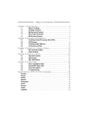
Table of Contents Chapter 1: Introduction 3 1.1 Before You Start 3 1.2 Package Checklist 3 1.3 Motherboard Features 4 1.4 Rear Panel Connectors 5 1.5 Motherboard Layout 6 Chapter 2: Hardware Installation 7 2.1 Installing Central Processing Unit (CPU 7 2.2 FAN Headers 9 2.3 Installing System Memory 10 2.4 Connectors and Slots 12 Chapter 3: Headers & Jumpers Setup 14 3.1 How ...
Table of Contents Chapter 1: Introduction 3 1.1 Before You Start 3 1.2 Package Checklist 3 1.3 Motherboard Features 4 1.4 Rear Panel Connectors 5 1.5 Motherboard Layout 6 Chapter 2: Hardware Installation 7 2.1 Installing Central Processing Unit (CPU 7 2.2 FAN Headers 9 2.3 Installing System Memory 10 2.4 Connectors and Slots 12 Chapter 3: Headers & Jumpers Setup 14 3.1 How ...
Setup Manual
Page 3
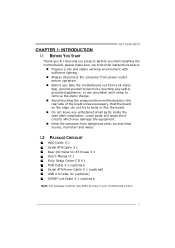
... the compute r from anti-static bag, ground yourse lf prope rly by area or your motherboard version. 3 Loose parts will cause short circuits which may differ by touching any unfastene d small parts inside the case afte r installation. GF7100P-M7S CHAPTER 1: INTRODUCTION 1.1 BEFORE YOU START Thank you take the mothe rboard out from dange...
... the compute r from anti-static bag, ground yourse lf prope rly by area or your motherboard version. 3 Loose parts will cause short circuits which may differ by touching any unfastene d small parts inside the case afte r installation. GF7100P-M7S CHAPTER 1: INTRODUCTION 1.1 BEFORE YOU START Thank you take the mothe rboard out from dange...
Setup Manual
Page 4
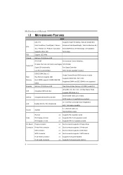
... port x1 Eachconnector supports 2 IDE device x4 Eachconnector supports 1 SATA devices x1 Supports front panel facilities x1 Supports front panel audio function 4 SATA Version 2.0specificationcompliant. Motherboard Manual 1.3 MOT HERBOARD FEAT URES SPEC CPU FSB LGA 775 Intel Core2Duo / Core2Quad / Celeron 4xx / Pentium D / Pentium 4 processor Supports 45nm CPU Support 1333 MHz Supports...
... port x1 Eachconnector supports 2 IDE device x4 Eachconnector supports 1 SATA devices x1 Supports front panel facilities x1 Supports front panel audio function 4 SATA Version 2.0specificationcompliant. Motherboard Manual 1.3 MOT HERBOARD FEAT URES SPEC CPU FSB LGA 775 Intel Core2Duo / Core2Quad / Celeron 4xx / Pentium D / Pentium 4 processor Supports 45nm CPU Support 1333 MHz Supports...
Setup Manual
Page 6
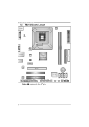
Motherboard Manual 1.5 MOT HERBOARD LAYOUT J US BKB 1 LGA775 JDVI 1 JUS BV1 CPU 1 J CFA N1 J ATXP WR1 DIMMA 1 DIMMA 2 JVGA1 I DE1 FDD1 J ATXP WR2 J US BLAN1 AUDIO1 J NFA N1 BIOS PE X1_1 GeForce 7100 nForce 630i LAN PE X16_1 BAT1 PCI1 Super I/O SATA 2 SATA 4 Codec PCI2 JAUDIOF1 JCDIN1 JSPDIF_OUT1 JPRNT1 JUSB2 JUSB3 JUSB4 JCOM1 J US BV2 S ATA 1 S ATA 3 JS FA N1 JC MOS1 JPANEL1 Not e: ■ represe nts the 1st pin. 6
Motherboard Manual 1.5 MOT HERBOARD LAYOUT J US BKB 1 LGA775 JDVI 1 JUS BV1 CPU 1 J CFA N1 J ATXP WR1 DIMMA 1 DIMMA 2 JVGA1 I DE1 FDD1 J ATXP WR2 J US BLAN1 AUDIO1 J NFA N1 BIOS PE X1_1 GeForce 7100 nForce 630i LAN PE X16_1 BAT1 PCI1 Super I/O SATA 2 SATA 4 Codec PCI2 JAUDIOF1 JCDIN1 JSPDIF_OUT1 JPRNT1 JUSB2 JUSB3 JUSB4 JCOM1 J US BV2 S ATA 1 S ATA 3 JS FA N1 JC MOS1 JPANEL1 Not e: ■ represe nts the 1st pin. 6
Setup Manual
Page 8
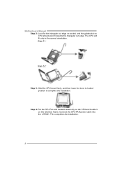
This completes the installation. 8 Step 2-1: Step 2-2: Step 3: Hold the CPU down firmly, and then lower the lever to locked position to complete the installation. Motherboard Manual Step 2: Look for the triangular cut edge on socket, and the golden dot on the retention frame. Connect the CPU FAN power cable into the JCFAN1. Step 4: Put the CPU Fan and heatsink assembly on the CPU and buckle it on CPU should point forwards this triangular cut edge. The CPU will fit only in the correct orientation.
This completes the installation. 8 Step 2-1: Step 2-2: Step 3: Hold the CPU down firmly, and then lower the lever to locked position to complete the installation. Motherboard Manual Step 2: Look for the triangular cut edge on socket, and the golden dot on the retention frame. Connect the CPU FAN power cable into the JCFAN1. Step 4: Put the CPU Fan and heatsink assembly on the CPU and buckle it on CPU should point forwards this triangular cut edge. The CPU will fit only in the correct orientation.
Setup Manual
Page 10
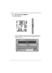
Align a DIMM on the slot such that the notch on the DIMM matches the break on the Slot. 10 Unlock a DIMM slot by pressing the retaining clips outward. Memory Modules 1. DIM MA1 DIM MA2 Motherboard Manual 2.3 INST ALLING SYST EM MEMORY A.
Align a DIMM on the slot such that the notch on the DIMM matches the break on the Slot. 10 Unlock a DIMM slot by pressing the retaining clips outward. Memory Modules 1. DIM MA1 DIM MA2 Motherboard Manual 2.3 INST ALLING SYST EM MEMORY A.
Setup Manual
Page 12
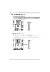
The IDE connector can connect a master and a slave drive, so y ou can connect up to two IDE devices. 40 39 21 12 Motherboard Manual 2.4 CONNECT ORS AND SLOT S FDD1: Floppy Disk Conne ctor The motherboard prov ides a standard floppy disk connector that prov ides PIO Mode 0~4, Bus Master, and Ultra DMA 33/66/100/133 f unctionality. This connector supports the prov ided f loppy drive ribbon cable. 34 33 2 1 IDE1: Hard Disk Conne ctor The motherboard has a 32-bit Enhanced PCI IDE Controller that supports 360K, 720K, 1.2M, 1.44M and 2.88M floppy disk ty pes.
The IDE connector can connect a master and a slave drive, so y ou can connect up to two IDE devices. 40 39 21 12 Motherboard Manual 2.4 CONNECT ORS AND SLOT S FDD1: Floppy Disk Conne ctor The motherboard prov ides a standard floppy disk connector that prov ides PIO Mode 0~4, Bus Master, and Ultra DMA 33/66/100/133 f unctionality. This connector supports the prov ided f loppy drive ribbon cable. 34 33 2 1 IDE1: Hard Disk Conne ctor The motherboard has a 32-bit Enhanced PCI IDE Controller that supports 360K, 720K, 1.2M, 1.44M and 2.88M floppy disk ty pes.
Setup Manual
Page 13
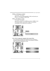
... ov er the traditional PCI architecture. PCI1 PCI2 13 PCI-Express 1.0a compliant. - PEX1_ 1 PEX16_1 PCI1~PCI2: Pe riphe ral Component Interconne ct Slots This motherboard is equipped with 2 standard PCI slots. GF7100P-M7S PEX16_1: PCI-Express x16 Slot -
... ov er the traditional PCI architecture. PCI1 PCI2 13 PCI-Express 1.0a compliant. - PEX1_ 1 PEX16_1 PCI1~PCI2: Pe riphe ral Component Interconne ct Slots This motherboard is equipped with 2 standard PCI slots. GF7100P-M7S PEX16_1: PCI-Express x16 Slot -
Setup Manual
Page 14
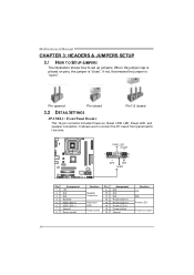
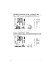
... drive 13 LED 14 Reset button 15 16 Assignment N/A N/A N/A Power LED (+) Power LED (+) Power LED (-) Power button Ground Functio n N/A N/A Power LED Power-on button 14 Motherboard Manual CHAPTER 3: HEADERS & JUMPERS SETUP 3.1 HOW T O SET UP JUMPERS The illustration shows how to connect the PC case's front panel switch f unctions.
... drive 13 LED 14 Reset button 15 16 Assignment N/A N/A N/A Power LED (+) Power LED (+) Power LED (-) Power button Ground Functio n N/A N/A Power LED Power-on button 14 Motherboard Manual CHAPTER 3: HEADERS & JUMPERS SETUP 3.1 HOW T O SET UP JUMPERS The illustration shows how to connect the PC case's front panel switch f unctions.
Setup Manual
Page 16
... cable on the PC f ront panel, and also can be connected with the PC f ront panel. This header allows only HD audio front panel connector; Motherboard Manual JUSB2/JUSB3/JUSB4: He ade rs for USB 2.0 Ports at Front Panel This header allows user to connect the front audio output cable with...
... cable on the PC f ront panel, and also can be connected with the PC f ront panel. This header allows only HD audio front panel connector; Motherboard Manual JUSB2/JUSB3/JUSB4: He ade rs for USB 2.0 Ports at Front Panel This header allows user to connect the front audio output cable with...
Setup Manual
Page 17
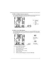
... saf e setting and the CMOS data, please carefully f ollow the procedures to "Pin 2-3 close ". 5. Set the jumper to "Pin 1-2 close ". 3. Remov e AC power line. 2. GF7100P-M7S JCDIN1: CD-RO M Audio-in Connector This connector allows user to connect the audio source f rom the v ariaty dev ices, like CD-ROM, DVD-ROM... Ground 3 Ground 4 Right Channel Input JCMO S1: Cle ar CMOS Heade r By placing the jumper on the AC. 6. Set the jumper to avoid damaging the motherboard. 13 Pin 1-2 Close: Normal Operation (default). 13 13 Pin 2-3 Close: Clear CMOS data. ※ Clear CMOS Proce dures: 1.
... saf e setting and the CMOS data, please carefully f ollow the procedures to "Pin 2-3 close ". 5. Set the jumper to "Pin 1-2 close ". 3. Remov e AC power line. 2. GF7100P-M7S JCDIN1: CD-RO M Audio-in Connector This connector allows user to connect the audio source f rom the v ariaty dev ices, like CD-ROM, DVD-ROM... Ground 3 Ground 4 Right Channel Input JCMO S1: Cle ar CMOS Heade r By placing the jumper on the AC. 6. Set the jumper to avoid damaging the motherboard. 13 Pin 1-2 Close: Normal Operation (default). 13 13 Pin 2-3 Close: Clear CMOS data. ※ Clear CMOS Proce dures: 1.
Setup Manual
Page 18
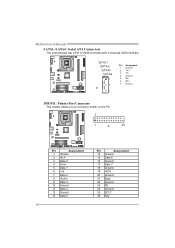
...~SATA4: Se rial ATA Connectors The motherboard has a PCI to connector printer on the PC. 2 1 25 Pin Assignment 1 -Strobe 2 -ALF 3 Data 0 4 -Error 5 Data 1 6 -Init 7 Data 2 8 -Scltin 9 Data 3 10 Ground 11 Data 4 12 ...
...~SATA4: Se rial ATA Connectors The motherboard has a PCI to connector printer on the PC. 2 1 25 Pin Assignment 1 -Strobe 2 -ALF 3 Data 0 4 -Error 5 Data 1 6 -Init 7 Data 2 8 -Scltin 9 Data 3 10 Ground 11 Data 4 12 ...
Setup Manual
Page 19
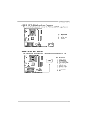
Pin Assignment 2 10 1 Carrier detect 2 Received data 3 T ransmitted data 1 9 4 Data terminal ready 5 Signal ground 6 Data set ready 7 Request to send 8 Clear to connect the PCI bracket SPDIF output header. 13 Pin Assignment 1 +5V 2 SPDIF_OUT 3 Ground JCO M1: Se rial port Conne ctor The motherboard has a Serial Port Connector for connecting RS-232 Port. GF7100P-M7S JSPDIF_O UT1: Digital Audio-out Conne ctor This connector allows user to send 9 Ring indicator 10 Key 19
Pin Assignment 2 10 1 Carrier detect 2 Received data 3 T ransmitted data 1 9 4 Data terminal ready 5 Signal ground 6 Data set ready 7 Request to send 8 Clear to connect the PCI bracket SPDIF output header. 13 Pin Assignment 1 +5V 2 SPDIF_OUT 3 Ground JCO M1: Se rial port Conne ctor The motherboard has a Serial Port Connector for connecting RS-232 Port. GF7100P-M7S JSPDIF_O UT1: Digital Audio-out Conne ctor This connector allows user to send 9 Ring indicator 10 Key 19
Setup Manual
Page 20
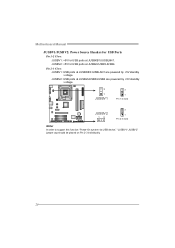
Pin 2-3 Close: JUSBV1: USB ports at JUSB2/JUSB3/JUSB4 are powered by +5V standby v oltage. 3 1 JUSBV1 3 1 Pin 1-2 close JUSBV2 13 3 1 Pin 2-3 close Note: In order to support this func tion "Power-On s ys tem via U SB device," "JUSBV1/ JUSBV2" jumper cap should be plac ed on Pin 2-3 indi viduall y. 20 JUSBV2: +5V for USB ports at JUSB2/JUSB3/JUSB4. Motherboard Manual JUSBV1/JUSBV2: Powe r Source Heade rs for USB Ports Pin 1-2 Close: JUSBV1: +5V for USB ports at JUSBKB1/JUSBLAN1. JUSBV2: USB ports at JUSBKB1/JUSBLAN1 are powered by +5V standby v oltage.
Pin 2-3 Close: JUSBV1: USB ports at JUSB2/JUSB3/JUSB4 are powered by +5V standby v oltage. 3 1 JUSBV1 3 1 Pin 1-2 close JUSBV2 13 3 1 Pin 2-3 close Note: In order to support this func tion "Power-On s ys tem via U SB device," "JUSBV1/ JUSBV2" jumper cap should be plac ed on Pin 2-3 indi viduall y. 20 JUSBV2: +5V for USB ports at JUSB2/JUSB3/JUSB4. Motherboard Manual JUSBV1/JUSBV2: Powe r Source Heade rs for USB Ports Pin 1-2 Close: JUSBV1: +5V for USB ports at JUSBKB1/JUSBLAN1. JUSBV2: USB ports at JUSBKB1/JUSBLAN1 are powered by +5V standby v oltage.
Setup Manual
Page 22
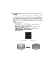
... data can be applied for the storage space of automatic backup that requires f ault tolerance and minimal capacity. Benefits: Prov ides 100% data redundancy. Motherboard Manual RAID 1: Every read and write is impaired during driv e rebuilds. Fault Tolerance: Yes. Should one driv e f ail, the controller switches to the other...
... data can be applied for the storage space of automatic backup that requires f ault tolerance and minimal capacity. Benefits: Prov ides 100% data redundancy. Motherboard Manual RAID 1: Every read and write is impaired during driv e rebuilds. Fault Tolerance: Yes. Should one driv e f ail, the controller switches to the other...
Setup Manual
Page 24
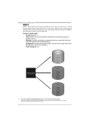
.... Features and Benefits Drives: Minimum 3. Uses: RAID 5 is placed on a different drive from those used to download the NVIDIA RAID User's Guide. 24 Motherboard Manual RAID 5: RAID 5 stripes both data and parity information across all the drives in the array.
.... Features and Benefits Drives: Minimum 3. Uses: RAID 5 is placed on a different drive from those used to download the NVIDIA RAID User's Guide. 24 Motherboard Manual RAID 5: RAID 5 stripes both data and parity information across all the drives in the array.
Setup Manual
Page 25
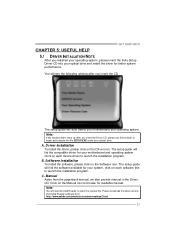
...device driver to open the manual file. The setup guide will auto detect your motherboard and operating system. Click on each software title to locate and execute the file SETUP.EXE under your optical drive. GF7100P-M7S CHAPTER 5: USEFUL HELP 5.1 DRIVER INST ALLAT ION NOT E After you installed... your operating system, please insert the Fully Setup Driver CD into your optical drive and install the driver for your motherboard and operating system. Manual Aside from ...
...device driver to open the manual file. The setup guide will auto detect your motherboard and operating system. Click on each software title to locate and execute the file SETUP.EXE under your optical drive. GF7100P-M7S CHAPTER 5: USEFUL HELP 5.1 DRIVER INST ALLAT ION NOT E After you installed... your operating system, please insert the Fully Setup Driver CD into your optical drive and install the driver for your motherboard and operating system. Manual Aside from ...
Setup Manual
Page 26
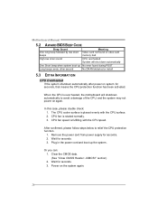
Motherboard Manual 5.2 AWARD BIOS BEEP CODE Beep Sound One long beep followed by two short beeps Meaning Video card not found during POST Long beeps every ... will shutdown automatically to relief the CPU protection function. 1. CPU fan is placed evenly with the CPU speed. CPU fan speed is over heated, the motherboard will shut down automatically One Short beep when system boot-up the system. When the CPU is fulfilling with the CPU surface. 2.
Motherboard Manual 5.2 AWARD BIOS BEEP CODE Beep Sound One long beep followed by two short beeps Meaning Video card not found during POST Long beeps every ... will shutdown automatically to relief the CPU protection function. 1. CPU fan is placed evenly with the CPU speed. CPU fan speed is over heated, the motherboard will shut down automatically One Short beep when system boot-up the system. When the CPU is fulfilling with the CPU surface. 2.

