
Setup Manual
Page 1
...pecially disclaims any purpose. The vendor makes no guarantee that interference will not be res ponsible for any implied warranties of this user's manual. D uplication of merchantability or fitness for any mis takes found to comply with the limits of a Class B digital devic e, purs...not occur in this publication, in part or in whole, is no representations or warranties with respec t to notify any party beforehand. GF7025-M2 Setup Manual FCC Information and Copyright This equipment has been tes ted and found in a particular ins tallation. T his equipment generates , uses ,...
...pecially disclaims any purpose. The vendor makes no guarantee that interference will not be res ponsible for any implied warranties of this user's manual. D uplication of merchantability or fitness for any mis takes found to comply with the limits of a Class B digital devic e, purs...not occur in this publication, in part or in whole, is no representations or warranties with respec t to notify any party beforehand. GF7025-M2 Setup Manual FCC Information and Copyright This equipment has been tes ted and found in a particular ins tallation. T his equipment generates , uses ,...

Setup Manual
Page 3
... the compute r from powe r outle t be nd or flex the board. „ Do not leave any unfastene d small parts inside the case afte r installation. GF7025-M2 CHAPTER 1: INTRODUCTION 1.1 BEFORE YOU START Thank you for ATX Case X 1 Use r's Manual X 1 Fully Se tup Drive r C D X 1 FDD Cable X 1 (optional) USB 2.0 Cable X1 (optional) S/PDIF out Cable X 1 (optional) 3
... the compute r from powe r outle t be nd or flex the board. „ Do not leave any unfastene d small parts inside the case afte r installation. GF7025-M2 CHAPTER 1: INTRODUCTION 1.1 BEFORE YOU START Thank you for ATX Case X 1 Use r's Manual X 1 Fully Se tup Drive r C D X 1 FDD Cable X 1 (optional) USB 2.0 Cable X1 (optional) S/PDIF out Cable X 1 (optional) 3

Setup Manual
Page 4
... / 66 / 100 / 133 Bus Master Mode supports PIO Mode 0~4, supports PIO Mode 0~4, IntegratedSerial ATA Controller IntegratedSerial ATA Controller Data transfer rates up to 3 Gb/s. Motherboard Manual 1.3 MOT HERBOARD FEAT URES Ver 5.x Ver 6.x CPU FSB Socket AM2 Socket AM2 AMDAthlon 64 / Athlon 64 FX / Athlon 64 x2 / AMDAthlon 64 / Athlon 64 FX...
... / 66 / 100 / 133 Bus Master Mode supports PIO Mode 0~4, supports PIO Mode 0~4, IntegratedSerial ATA Controller IntegratedSerial ATA Controller Data transfer rates up to 3 Gb/s. Motherboard Manual 1.3 MOT HERBOARD FEAT URES Ver 5.x Ver 6.x CPU FSB Socket AM2 Socket AM2 AMDAthlon 64 / Athlon 64 FX / Athlon 64 x2 / AMDAthlon 64 / Athlon 64 FX...

Setup Manual
Page 6
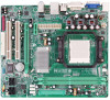
... trans mission onl y. [ D-Sub VGA Port Transmit anal og vi deo signals to digital display devices s uch as flat panel LCDs or digital projectors. Motherboard Manual 1.4 REAR PANEL CONNECT ORS X PS/2 Mouse Port Y PS/2 Keyboard Port Z DVI-D VGA Port The Digital Visual Interface (DVI) is a video i nterface trans mitting digital video...
... trans mission onl y. [ D-Sub VGA Port Transmit anal og vi deo signals to digital display devices s uch as flat panel LCDs or digital projectors. Motherboard Manual 1.4 REAR PANEL CONNECT ORS X PS/2 Mouse Port Y PS/2 Keyboard Port Z DVI-D VGA Port The Digital Visual Interface (DVI) is a video i nterface trans mitting digital video...

Setup Manual
Page 8
Motherboard Manual CHAPTER 2: HARDWARE INSTALLATION 2.1 INST ALLING CENT RAL PROCESSING UNIT (CPU) Step 1: Remove the socket protection cap. Step 3: Look for the white triangle on socket, and the gold triangle on CPU should point towards this white triangle. The CPU will fit only in the correct orientation. 8 Step 2: Pull the lever toward direction A from the socket and then raise the lever up to a 90-degree angle.
Motherboard Manual CHAPTER 2: HARDWARE INSTALLATION 2.1 INST ALLING CENT RAL PROCESSING UNIT (CPU) Step 1: Remove the socket protection cap. Step 3: Look for the white triangle on socket, and the gold triangle on CPU should point towards this white triangle. The CPU will fit only in the correct orientation. 8 Step 2: Pull the lever toward direction A from the socket and then raise the lever up to a 90-degree angle.

Setup Manual
Page 10
... different according to the fan manufacturer. The fan cable and connector may be connected to pin#1. The J SFAN1 and JNFAN1 s upport 3-pin head connectors. Motherboard Manual 2.2 FAN HEADERS These fan headers support cooling-fans built in the computer. Connect the fan cable to the connector while matching the black wire to...
... different according to the fan manufacturer. The fan cable and connector may be connected to pin#1. The J SFAN1 and JNFAN1 s upport 3-pin head connectors. Motherboard Manual 2.2 FAN HEADERS These fan headers support cooling-fans built in the computer. Connect the fan cable to the connector while matching the black wire to...

Setup Manual
Page 12
... X Disabled X O Enabled O O (O means memory installed, X means memory not installed.) The DRAM bus width of the same density in pair, shown in the f ollowing table. Motherboard Manual B. Memory Capacity DIMM Socket Location DIMMA1 DIMMB1 DDR2 Module 256MB/512MB/1GB/2GB 256MB/512MB/1GB/2GB Total Memory Size Max is 4GB. C.
... X Disabled X O Enabled O O (O means memory installed, X means memory not installed.) The DRAM bus width of the same density in pair, shown in the f ollowing table. Motherboard Manual B. Memory Capacity DIMM Socket Location DIMMA1 DIMMB1 DDR2 Module 256MB/512MB/1GB/2GB 256MB/512MB/1GB/2GB Total Memory Size Max is 4GB. C.

Setup Manual
Page 14
... is equipped with 2 standard PCI slots. PCI-EX1_1: PCI-Express x1 Slot - PCI-Express supports a raw bit-rate of 8GB/s totally. PCI1 PCI2 14 Motherboard Manual PCI-EX16: PCI-Express x16 Slot - PCI-EX1_1 PCI-EX16 PCI1~PCI2: Pe riphe ral Component Interconne ct Slots This motherboard is a bus standard for...
... is equipped with 2 standard PCI slots. PCI-EX1_1: PCI-Express x1 Slot - PCI-Express supports a raw bit-rate of 8GB/s totally. PCI1 PCI2 14 Motherboard Manual PCI-EX16: PCI-Express x16 Slot - PCI-EX1_1 PCI-EX16 PCI1~PCI2: Pe riphe ral Component Interconne ct Slots This motherboard is a bus standard for...

Setup Manual
Page 16
Motherboard Manual JATXPWR1: ATX Powe r Source C onne ctor This connector allows user to connect 24-pin power connector on the ATX power supply. 12 24 Pin Assignment ...
Motherboard Manual JATXPWR1: ATX Powe r Source C onne ctor This connector allows user to connect 24-pin power connector on the ATX power supply. 12 24 Pin Assignment ...

Setup Manual
Page 18
... Jack Sense JCDIN1: CD-RO M Audio-in Connector This connector allows user to connect the front audio output cable with the PC f ront panel. Motherboard Manual JAUDIO F1: Front Panel Audio Heade r This header allows user to connect the audio source f rom the v ariaty dev ices, like CD-ROM, DVD-ROM...
... Jack Sense JCDIN1: CD-RO M Audio-in Connector This connector allows user to connect the front audio output cable with the PC f ront panel. Motherboard Manual JAUDIO F1: Front Panel Audio Heade r This header allows user to connect the audio source f rom the v ariaty dev ices, like CD-ROM, DVD-ROM...

Setup Manual
Page 20
Motherboard Manual JPRNT1: Printe r Port Connector This header allows you to connector printer on the PC. 2 1 25 Pin Assignment 1 -Strobe 2 -ALF 3 Data 0 4 -Error 5 Data 1 6 -Init 7 Data 2 8 -Scltin 9 ...
Motherboard Manual JPRNT1: Printe r Port Connector This header allows you to connector printer on the PC. 2 1 25 Pin Assignment 1 -Strobe 2 -ALF 3 Data 0 4 -Error 5 Data 1 6 -Init 7 Data 2 8 -Scltin 9 ...

Setup Manual
Page 22
.... Fault Tolerance: Yes. Perf ormance is corrupted or becomes unavailable because of a hardware failure. Motherboard Manual RAID 1: Every read and write is ideal f or small databases or any other application that eliminates tedious manual backups to the other drive. Drawbacks: Requires 2 driv es for high-availability solutions, or as a form...
.... Fault Tolerance: Yes. Perf ormance is corrupted or becomes unavailable because of a hardware failure. Motherboard Manual RAID 1: Every read and write is ideal f or small databases or any other application that eliminates tedious manual backups to the other drive. Drawbacks: Requires 2 driv es for high-availability solutions, or as a form...

Setup Manual
Page 24
... of good perf ormance, good f ault tolerance, and high capacity and storage efficiency. Drawbacks: Individual block data transfer rate same as a single disk. Motherboard Manual RAID 5: RAID 5 stripes both data and parity information across all the drives in the array. It writes data and parity blocks across three or more...
... of good perf ormance, good f ault tolerance, and high capacity and storage efficiency. Drawbacks: Individual block data transfer rate same as a single disk. Motherboard Manual RAID 5: RAID 5 stripes both data and parity information across all the drives in the array. It writes data and parity blocks across three or more...

Setup Manual
Page 25
GF7025-M2 CHAPTER 5: USEFUL HELP 5.1 DRIVER INST ALLAT ION NOT E After you installed your operating system, please insert the Fully Setup Driver CD into your system, click ... the Driver icon. Pleas e download the latest version of Acrobat Reader soft ware from the paperback manual, we also provide manual in the Driver CD. Driver Installation To install the driver, please click on the Manual icon to open the manual file. Software Installation To install the software, please click on the Software icon...
GF7025-M2 CHAPTER 5: USEFUL HELP 5.1 DRIVER INST ALLAT ION NOT E After you installed your operating system, please insert the Fully Setup Driver CD into your system, click ... the Driver icon. Pleas e download the latest version of Acrobat Reader soft ware from the paperback manual, we also provide manual in the Driver CD. Driver Installation To install the driver, please click on the Manual icon to open the manual file. Software Installation To install the software, please click on the Software icon...

Setup Manual
Page 26
... on the system again. 26 Clear the CMOS data. (See "Close CMOS Header: JCMOS1" section) 2. Remove the power cord from power supply for seconds. 2. Motherboard Manual 5.2 AWARD BIOS BEEP CODE Beep Sound One long beep followed by two short beeps Meaning Video card not found during POST Long beeps every other...
... on the system again. 26 Clear the CMOS data. (See "Close CMOS Header: JCMOS1" section) 2. Remove the power cord from power supply for seconds. 2. Motherboard Manual 5.2 AWARD BIOS BEEP CODE Beep Sound One long beep followed by two short beeps Meaning Video card not found during POST Long beeps every other...

Setup Manual
Page 28
...' computer systems if the setting is not appropriate when testing and results in the About panel, you do not need to install DirectX 8.1.) 28 Motherboard Manual CHAPTER 6: WARPSPEEDER™ III 6.1 INT RODUCT ION [WarpSpeeder™ III], a new powerful control utility, features three user-friendly functions including Overclock Manager, Overvoltage Manager, and...
...' computer systems if the setting is not appropriate when testing and results in the About panel, you do not need to install DirectX 8.1.) 28 Motherboard Manual CHAPTER 6: WARPSPEEDER™ III 6.1 INT RODUCT ION [WarpSpeeder™ III], a new powerful control utility, features three user-friendly functions including Overclock Manager, Overvoltage Manager, and...

Setup Manual
Page 29
GF7025-M2 6.3 INST ALLAT ION 1. Click "Finish" button. When you see the following dialog will change according to i n stall . 2. Please click "Next" button and follow the default procedure to your motherboard on hand. 29 Usage : The following figures are only for reference, the screen printed in setup procedure, it means setup is completed. Execute the setup execution file, and then the following dialog in this user manual will pop up.
GF7025-M2 6.3 INST ALLAT ION 1. Click "Finish" button. When you see the following dialog will change according to i n stall . 2. Please click "Next" button and follow the default procedure to your motherboard on hand. 29 Usage : The following figures are only for reference, the screen printed in setup procedure, it means setup is completed. Execute the setup execution file, and then the following dialog in this user manual will pop up.

Setup Manual
Page 30
... Panel. Main Panel If you double-click the desktop icon, [WarpSpeeder™ III] will appear on the desktop, just like the icon shown below. Motherboard Manual 6.4 WARPSPEEDER™ III 1. the utility's first window you can launch the [WarpSpeeder™ III] utility simply by double-clicking the desktop icon. 2. b. Contains About, Voltage...
... Panel. Main Panel If you double-click the desktop icon, [WarpSpeeder™ III] will appear on the desktop, just like the icon shown below. Motherboard Manual 6.4 WARPSPEEDER™ III 1. the utility's first window you can launch the [WarpSpeeder™ III] utility simply by double-clicking the desktop icon. 2. b. Contains About, Voltage...

Setup Manual
Page 32
... unstable, click on "OK" to the hardware default se tti ng . Then system will restore to proceed. "Verify": If you use the "Manual Adjust" bar to the hardware default setting. 32 d. If the testing is over 110 %. "Recovery": Click this button and [WarpSpeeder™ III...fail-safe rebooting. "V3 Engine"/"V6 Engine"/"V9 Engine": Provide user the ability to notify you overclock by using Watchdog function. Warning: Manually overclock is potentially dangerous, especially when the ov erclocking percentage is ok, then the current frequency will restore all values to adjust the...
... unstable, click on "OK" to the hardware default se tti ng . Then system will restore to proceed. "Verify": If you use the "Manual Adjust" bar to the hardware default setting. 32 d. If the testing is over 110 %. "Recovery": Click this button and [WarpSpeeder™ III...fail-safe rebooting. "V3 Engine"/"V6 Engine"/"V9 Engine": Provide user the ability to notify you overclock by using Watchdog function. Warning: Manually overclock is potentially dangerous, especially when the ov erclocking percentage is ok, then the current frequency will restore all values to adjust the...

Setup Manual
Page 34
... chipset is not on board, the correlative button in Main panel will be highlighted and the About Panel will not interfere other panels' functions. Motherboard Manual 5. You can also get model name and detail information in Main Panel, the button will be disabled, but will show up as the following figure...
... chipset is not on board, the correlative button in Main panel will be highlighted and the About Panel will not interfere other panels' functions. Motherboard Manual 5. You can also get model name and detail information in Main Panel, the button will be disabled, but will show up as the following figure...

