
GeForce 6100-M9 user's manual
Page 2
Table of Contents Chapter 1: Introduction 1 1.1 Motherboard Features 1 1.2 Layout and Components 4 Chapter 2: Hardware Installation 5 2.1 Installing Central Processing Unit (CPU 5 2.2 FAN Headers 6 2.3 Installing System Memory 7 2.4 Connectors and Slots 9 Chapter 3: Headers & Jumpers Setup 11 3.1 ...
Table of Contents Chapter 1: Introduction 1 1.1 Motherboard Features 1 1.2 Layout and Components 4 Chapter 2: Hardware Installation 5 2.1 Installing Central Processing Unit (CPU 5 2.2 FAN Headers 6 2.3 Installing System Memory 7 2.4 Connectors and Slots 9 Chapter 3: Headers & Jumpers Setup 11 3.1 ...

GeForce 6100-M9 user's manual
Page 3
..." function 1 Supports HyperTransport Technology up to 2000MT/s. Chipset North Bridge: nVIDIA GeForce6100. Low Pin Count Interface. Note: Does not support Windows 98SE and Windows ME. GeForce 6100-M9 CHAPTER 1: INTRODUCTION 1.1 MOTHERBOARD FEATURES CPU Supports Socket 939. Supports AMD Athlon 64 FX/ Athlon 64/ Athlon 64 X2 processor.
..." function 1 Supports HyperTransport Technology up to 2000MT/s. Chipset North Bridge: nVIDIA GeForce6100. Low Pin Count Interface. Note: Does not support Windows 98SE and Windows ME. GeForce 6100-M9 CHAPTER 1: INTRODUCTION 1.1 MOTHERBOARD FEATURES CPU Supports Socket 939. Supports AMD Athlon 64 FX/ Athlon 64/ Athlon 64 X2 processor.
GeForce 6100-M9 user's manual
Page 11
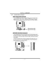
...2 IDE1/IDE2: Hard Disk Connectors The motherboard has a 32-bit Enhanced PCI IDE Controller that supports 360K, 720K, 1.2M, 1.44M and 2.88M floppy disk types. The first hard drive should always be connected to four hard disk drives. GeForce 6100-M9 2.4 CONNECTORS AND SLOTS FDD1: Floppy Disk ...Connector The motherboard provides a standard floppy disk connector that provides PIO Mode 0~4, Bus Master, and Ultra DMA 33/66/100/133...
...2 IDE1/IDE2: Hard Disk Connectors The motherboard has a 32-bit Enhanced PCI IDE Controller that supports 360K, 720K, 1.2M, 1.44M and 2.88M floppy disk types. The first hard drive should always be connected to four hard disk drives. GeForce 6100-M9 2.4 CONNECTORS AND SLOTS FDD1: Floppy Disk ...Connector The motherboard provides a standard floppy disk connector that provides PIO Mode 0~4, Bus Master, and Ultra DMA 33/66/100/133...
GeForce 6100-M9 user's manual
Page 12
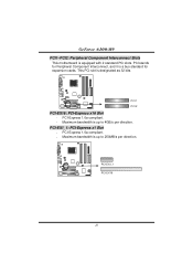
PCI-Express 1.0a compliant. - Maximum bandwidth is up to 250MB/s per direction. PCI1 PCI2 PCI-EX16: PCI-Express x16 Slot - PCI-Express 1.0a compliant. - GeForce 6100-M9 PCI1~PCI2: Peripheral Component Interconnect Slots This motherboard is a bus standard for expansion cards. PCI stands for Peripheral Component Interconnect, and it is equipped with 2 standard PCI slots. Maximum bandwidth is designated as 32 bits. PCI-EX1_1 PCI-EX16 10 PCI-EX1_1: PCI-Express x1 Slot - This PCI slot is up to 4GB/s per direction.
PCI-Express 1.0a compliant. - Maximum bandwidth is up to 250MB/s per direction. PCI1 PCI2 PCI-EX16: PCI-Express x16 Slot - PCI-Express 1.0a compliant. - GeForce 6100-M9 PCI1~PCI2: Peripheral Component Interconnect Slots This motherboard is a bus standard for expansion cards. PCI stands for Peripheral Component Interconnect, and it is equipped with 2 standard PCI slots. Maximum bandwidth is designated as 32 bits. PCI-EX1_1 PCI-EX16 10 PCI-EX1_1: PCI-Express x1 Slot - This PCI slot is up to 4GB/s per direction.
GeForce 6100-M9 user's manual
Page 15
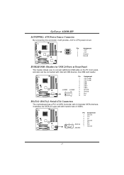
... 1 9 10 NC JSATA1~JSATA2: Serial ATA Connectors The motherboard has a PCI to SATA Controller with 2 channels SATA interface, it will provide +12V to connect additional USB cable on the PC front panel, and also can be connected with transfer rate of 3GB/s. GeForce 6100-M9 JATXPWR2: ATX Power Source Connector By connecting this connector...
... 1 9 10 NC JSATA1~JSATA2: Serial ATA Connectors The motherboard has a PCI to SATA Controller with 2 channels SATA interface, it will provide +12V to connect additional USB cable on the PC front panel, and also can be connected with transfer rate of 3GB/s. GeForce 6100-M9 JATXPWR2: ATX Power Source Connector By connecting this connector...
GeForce 6100-M9 user's manual
Page 18
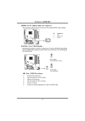
.... 16 Wait for five seconds. 4. GeForce 6100-M9 JSPDIF_OUT1: Digital Audio-out Connector This connector allows user to connect the PCI bracket SPDIF output header. 1 3 Pin Assignment 1 +5V 2 SPDIF_OUT 3 Ground JCMOS1: Clear CMOS Header By placing the jumper on the AC. 6. Set the jumper to avoid damaging the motherboard. 1 3 Pin 1-2 Close: Normal Operation (Default...
.... 16 Wait for five seconds. 4. GeForce 6100-M9 JSPDIF_OUT1: Digital Audio-out Connector This connector allows user to connect the PCI bracket SPDIF output header. 1 3 Pin Assignment 1 +5V 2 SPDIF_OUT 3 Ground JCMOS1: Clear CMOS Header By placing the jumper on the AC. 6. Set the jumper to avoid damaging the motherboard. 1 3 Pin 1-2 Close: Normal Operation (Default...
GeForce 6100-M9 user's manual
Page 19
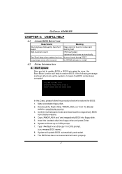
...BIOS into floppy drive and press Enter. 6. System will boot-up to restore BIOS. Download the Flash Utility "AWDFLASH.exe" from Biostar website. 4. System will work properly. 17 Make a bootable floppy disk. 2. Type "Awdflash xxxx.bf/sn/py/r" in DOS ...GeForce 6100-M9 CHAPTER 4: USEFUL HELP 4.1 AWARD BIOS BEEP CODE Beep Sound One long beep followed by virus, the Boot-Block function will help to DOS prompt. 7. In this Case, please follow the procedure below to restore the BIOS: 1. Confirm motherboard model and download the respectively BIOS from the Biostar website: www.biostar...
...BIOS into floppy drive and press Enter. 6. System will boot-up to restore BIOS. Download the Flash Utility "AWDFLASH.exe" from Biostar website. 4. System will work properly. 17 Make a bootable floppy disk. 2. Type "Awdflash xxxx.bf/sn/py/r" in DOS ...GeForce 6100-M9 CHAPTER 4: USEFUL HELP 4.1 AWARD BIOS BEEP CODE Beep Sound One long beep followed by virus, the Boot-Block function will help to DOS prompt. 7. In this Case, please follow the procedure below to restore the BIOS: 1. Confirm motherboard model and download the respectively BIOS from the Biostar website: www.biostar...
GeForce 6100-M9 user's manual
Page 20
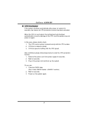
...When the CPU is fulfilling with the CPU surface. 2. In this case, please double check: 1. CPU fan speed is over heated, the motherboard will shutdown automatically to relief the CPU protection function. 1. Clear the CMOS data. (See "Close CMOS Header: JCMOS1" section) 2. CPU Overheated... cord from power supply for seconds. 3. Or you can: 1. Wait for seconds. 2. Plug in the power cord and boot up the system. GeForce 6100-M9 B. Wait for seconds, that means the CPU protection function has been activated. CPU fan is placed evenly with the CPU speed. After confirmed, please ...
...When the CPU is fulfilling with the CPU surface. 2. In this case, please double check: 1. CPU fan speed is over heated, the motherboard will shutdown automatically to relief the CPU protection function. 1. Clear the CMOS data. (See "Close CMOS Header: JCMOS1" section) 2. CPU Overheated... cord from power supply for seconds. 3. Or you can: 1. Wait for seconds. 2. Plug in the power cord and boot up the system. GeForce 6100-M9 B. Wait for seconds, that means the CPU protection function has been activated. CPU fan is placed evenly with the CPU speed. After confirmed, please ...
GeForce 6100-M9 user's manual
Page 23
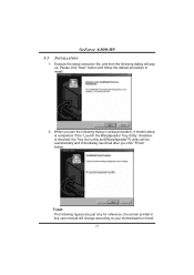
If the "Launch the WarpSpeeder Tray Utility" checkbox is completed. Please click "Next" button and follow the default procedure to your motherboard on hand. 21 Usage: The following dialog will change according to install. 2. When you click "Finish" button. Execute the setup execution file, and then the ... Icon utility and [WarpSpeeder™] utility will be automatically and immediately launched after you see the following dialog in this user manual will pop up. GeForce 6100-M9 5.3 INSTALLATION 1.
If the "Launch the WarpSpeeder Tray Utility" checkbox is completed. Please click "Next" button and follow the default procedure to your motherboard on hand. 21 Usage: The following dialog will change according to install. 2. When you click "Finish" button. Execute the setup execution file, and then the ... Icon utility and [WarpSpeeder™] utility will be automatically and immediately launched after you see the following dialog in this user manual will pop up. GeForce 6100-M9 5.3 INSTALLATION 1.
BIOS SETUP MANUAL
Page 18
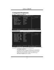
... a primary and/or secondary add-in IDE interface. Select "Disabled" to deactivate an interface if you a submenu with the following options: OnChip IDE Channel 0/1 The motherboard chipset contains a PCI IDE interface with support for two IDE channels. The Choices: Enabled (default), Disabled. 17 Integrated Peripherals IDE Function Setup If you highlight... "IDE Function Setup" label and then press the enter key, it will take you are going to activate the first and/or second IDE interface. GeForce 6100-M9 5 Integrated Peripherals Figure 5.
... a primary and/or secondary add-in IDE interface. Select "Disabled" to deactivate an interface if you a submenu with the following options: OnChip IDE Channel 0/1 The motherboard chipset contains a PCI IDE interface with support for two IDE channels. The Choices: Enabled (default), Disabled. 17 Integrated Peripherals IDE Function Setup If you highlight... "IDE Function Setup" label and then press the enter key, it will take you are going to activate the first and/or second IDE interface. GeForce 6100-M9 5 Integrated Peripherals Figure 5.


