Bios Setup
Page 2
T his AMI BIOS supports Version 1.03 of this motherboard. Power management features are also included in the AMI BIOS Setup program on this manual is turned off. G41U3G BIOS Manual BIOS Setup Introduction T he purpose of the EPA Green PC specification. Basic Input-Output System (BIOS) determines what a computer can also be managed...
T his AMI BIOS supports Version 1.03 of this motherboard. Power management features are also included in the AMI BIOS Setup program on this manual is turned off. G41U3G BIOS Manual BIOS Setup Introduction T he purpose of the EPA Green PC specification. Basic Input-Output System (BIOS) determines what a computer can also be managed...
Bios Setup
Page 3
... Interconn ect) local bus speci fication. DRAM S upport DDR3 SDRAM (Double Data Rate III Synchronous DRAM) is providing a brief description of the motherboard. Using Setup When starting up the computer, press during the Power-On Self-Test (POST) to ensure optimum performan ce of the selected item....continuously updated. We will see General Help description at the bottom right corner, and you will not be responsible for your reference only. G41U3G BIOS Manual PCI Bus Support T his AMI BIOS supports the Intel CPU. Navigation Keys for that may be chang ed without notice. If...
... Interconn ect) local bus speci fication. DRAM S upport DDR3 SDRAM (Double Data Rate III Synchronous DRAM) is providing a brief description of the motherboard. Using Setup When starting up the computer, press during the Power-On Self-Test (POST) to ensure optimum performan ce of the selected item....continuously updated. We will see General Help description at the bottom right corner, and you will not be responsible for your reference only. G41U3G BIOS Manual PCI Bus Support T his AMI BIOS supports the Intel CPU. Navigation Keys for that may be chang ed without notice. If...
Bios Setup
Page 15
... add a pointer to an OEMB table in headless mode, both BIOS and operating system (e.g. Windows Server 2003) must support headless operation. G41U3G BIOS Manual Suspend mode T he item allows you to determine whether to invoke VGA BIOS post on S3 Resume T he item allows you...APIC support T his is a server-speci fic feature. Options: S1 (POS) (Default) Power on Suspend S3 (ST R) Suspend to enable or disable the motherboard's APIC (Advan ced Programmable Interrupt Controller). A headless server is used to RAM Auto POS+STR Repost Video on S3/ST R resume. Options: No (Default...
... add a pointer to an OEMB table in headless mode, both BIOS and operating system (e.g. Windows Server 2003) must support headless operation. G41U3G BIOS Manual Suspend mode T he item allows you to determine whether to invoke VGA BIOS post on S3 Resume T he item allows you...APIC support T his is a server-speci fic feature. Options: S1 (POS) (Default) Power on Suspend S3 (ST R) Suspend to enable or disable the motherboard's APIC (Advan ced Programmable Interrupt Controller). A headless server is used to RAM Auto POS+STR Repost Video on S3/ST R resume. Options: No (Default...
Bios Setup
Page 16
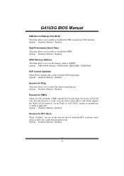
... Disabled (Default) / Enabled HPET Memory Address T his item allows you to Full ON state. Set the Wake on LAN (WOL) jumper on motherboard to enable or disabled the USB resume from S3/S4 function. Options: Disabled (Default) / Enabled Resume On RTC Alarm When " Enabled", you to... enable if applicabl e. Options: Disabled (Default) / Enabled 15 G41U3G BIOS Manual USB Dev ice Wakeup from S3/S4 T his item allows you can set the memory address of HPET . Options: FED00000h (Default) / FED01000h ...
... Disabled (Default) / Enabled HPET Memory Address T his item allows you to Full ON state. Set the Wake on LAN (WOL) jumper on motherboard to enable or disabled the USB resume from S3/S4 function. Options: Disabled (Default) / Enabled Resume On RTC Alarm When " Enabled", you to... enable if applicabl e. Options: Disabled (Default) / Enabled 15 G41U3G BIOS Manual USB Dev ice Wakeup from S3/S4 T his item allows you can set the memory address of HPET . Options: FED00000h (Default) / FED01000h ...
Setup Manual
Page 2
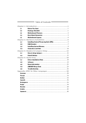
Table of Contents Chapter 1: Introduction 1 1.1 Before You Start 1 1.2 Package Checklist 1 1.3 Motherboard Features 2 1.4 Rear Panel Connectors 3 1.5 Motherboard Layout 4 Chapter 2: Hardware Installation 5 2.1 Installing Central Processing Unit (CPU 5 2.2 FAN Headers 7 2.3 Installing System Memory 8 2.4 Connectors and Slots 10 Chapter 3: Headers & Jumpers Setup 13 3.1 How to ...
Table of Contents Chapter 1: Introduction 1 1.1 Before You Start 1 1.2 Package Checklist 1 1.3 Motherboard Features 2 1.4 Rear Panel Connectors 3 1.5 Motherboard Layout 4 Chapter 2: Hardware Installation 5 2.1 Installing Central Processing Unit (CPU 5 2.2 FAN Headers 7 2.3 Installing System Memory 8 2.4 Connectors and Slots 10 Chapter 3: Headers & Jumpers Setup 13 3.1 How to ...
Setup Manual
Page 3
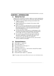
CHAPTER 1: INTRODUCTION G41U3G 1.1 BEFORE YOU START Thank you take the motherboard out from anti-static bag, ground yourself properly by touching any unfastened small parts inside ) FDD Cable X 1 (optional) USB 2.0 Cable X1 (optional) Serial ATA Power ... charge. „ Avoid touching the components on the edge, do not try to area or your motherboard version. 1 Hold the board on motherboard or the rear side of the board unless necessary. Before you start installing the motherboard, please make sure you follow the instructions below: „ Prepare a dry and stable working environment...
CHAPTER 1: INTRODUCTION G41U3G 1.1 BEFORE YOU START Thank you take the motherboard out from anti-static bag, ground yourself properly by touching any unfastened small parts inside ) FDD Cable X 1 (optional) USB 2.0 Cable X1 (optional) Serial ATA Power ... charge. „ Avoid touching the components on the edge, do not try to area or your motherboard version. 1 Hold the board on motherboard or the rear side of the board unless necessary. Before you start installing the motherboard, please make sure you follow the instructions below: „ Prepare a dry and stable working environment...
Setup Manual
Page 4
Motherboard Manual 1.3 MOTHERBOARD FEATURES SPEC LGA 775 Supports Hyper-Threading / Execute Disable Bit / Intel Core2Duo / Core2Quad / Enhanced Intel SpeedStep® / Intel Architecture-64 / CPU Pentium Dual-Core / Celeron ...
Motherboard Manual 1.3 MOTHERBOARD FEATURES SPEC LGA 775 Supports Hyper-Threading / Execute Disable Bit / Intel Core2Duo / Core2Quad / Enhanced Intel SpeedStep® / Intel Architecture-64 / CPU Pentium Dual-Core / Celeron ...
Setup Manual
Page 6
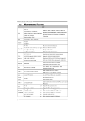
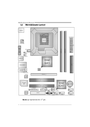
BAT1 SATA4 SATA3 4 Motherboard Manual 1.5 MOTHERBOARD LAYOUT KBMS1 LGA775 ATX PWR2 CPU1 ATXPWR1 DDR3_A1 DDR3_B1 IDE1 V GA1 CPU_FAN1 JUSBV1 JUSBV2 USB3_0 RJ45USB1 Intel G41 AUD IO1 F_AUDIO1 LAN Super I/O Codec BIOS PEX16_1 PCI1 J_PRIN T1 PCI2 J_ COM1 FDD1 Intel ICH7 F_ USB1 SYS_FAN1 JU SBV3 F_USB2 PANEL1 JCMOS1 SATA1 S ATA2 Note: ■ represents the 1st pin.
BAT1 SATA4 SATA3 4 Motherboard Manual 1.5 MOTHERBOARD LAYOUT KBMS1 LGA775 ATX PWR2 CPU1 ATXPWR1 DDR3_A1 DDR3_B1 IDE1 V GA1 CPU_FAN1 JUSBV1 JUSBV2 USB3_0 RJ45USB1 Intel G41 AUD IO1 F_AUDIO1 LAN Super I/O Codec BIOS PEX16_1 PCI1 J_PRIN T1 PCI2 J_ COM1 FDD1 Intel ICH7 F_ USB1 SYS_FAN1 JU SBV3 F_USB2 PANEL1 JCMOS1 SATA1 S ATA2 Note: ■ represents the 1st pin.
Setup Manual
Page 8
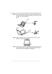
Motherboard Manual Step 2: Look for the triangular cut edge. This completes the installation. 6 Step 2-1: Step 2-2: Step 3: Hold the CPU down firmly, and then lower the lever to locked position to complete the installation. Connect the CPU FAN power cable into the CPU_FAN1. Step 4: Put the CPU Fan and heatsink assembly on the CPU and buckle it on CPU should point forwards this triangular cut edge on socket, and the golden dot on the retention frame. The CPU will fit only in the correct orientation.
Motherboard Manual Step 2: Look for the triangular cut edge. This completes the installation. 6 Step 2-1: Step 2-2: Step 3: Hold the CPU down firmly, and then lower the lever to locked position to complete the installation. Connect the CPU FAN power cable into the CPU_FAN1. Step 4: Put the CPU Fan and heatsink assembly on the CPU and buckle it on CPU should point forwards this triangular cut edge on socket, and the golden dot on the retention frame. The CPU will fit only in the correct orientation.
Setup Manual
Page 10
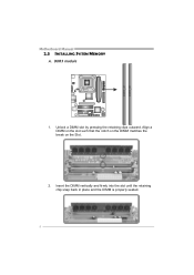
Align a DIMM on the slot such that the notch on the DIMM matches the break on the Slot. 2. Insert the DIMM vertically and firmly into the slot until the retaining chip snap back in place and the DIMM is properly seated. 8 DDR3_A1 DDR3_B1 Motherboard Manual 2.3 INSTALLING SYSTEM MEMORY A. DDR3 module 1. Unlock a DIMM slot by pressing the retaining clips outward.
Align a DIMM on the slot such that the notch on the DIMM matches the break on the Slot. 2. Insert the DIMM vertically and firmly into the slot until the retaining chip snap back in place and the DIMM is properly seated. 8 DDR3_A1 DDR3_B1 Motherboard Manual 2.3 INSTALLING SYSTEM MEMORY A. DDR3 module 1. Unlock a DIMM slot by pressing the retaining clips outward.
Setup Manual
Page 12
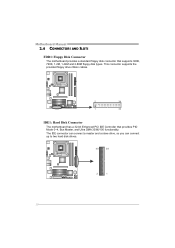
The IDE connector can connect a master and a slave drive, so you can connect up to two hard disk drives. 40 39 2 1 10 This connector supports the provided floppy drive ribbon cables. 2 34 1 33 IDE1: Hard Disk Connector The motherboard has a 32-bit Enhanced PCI IDE Controller that supports 360K, 720K, 1.2M, 1.44M and 2.88M floppy disk types. Motherboard Manual 2.4 CONNECTORS AND SLOTS FDD1: Floppy Disk Connector The motherboard provides a standard floppy disk connector that provides PIO Mode 0~4, Bus Master, and Ultra DMA 33/66/100 functionality.
The IDE connector can connect a master and a slave drive, so you can connect up to two hard disk drives. 40 39 2 1 10 This connector supports the provided floppy drive ribbon cables. 2 34 1 33 IDE1: Hard Disk Connector The motherboard has a 32-bit Enhanced PCI IDE Controller that supports 360K, 720K, 1.2M, 1.44M and 2.88M floppy disk types. Motherboard Manual 2.4 CONNECTORS AND SLOTS FDD1: Floppy Disk Connector The motherboard provides a standard floppy disk connector that provides PIO Mode 0~4, Bus Master, and Ultra DMA 33/66/100 functionality.
Setup Manual
Page 14
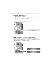
Maximum theoretical realized bandwidth of 4GB/s simultaneously per direction, for expansion cards. PCI1 PCI2 12 This PCI slot is equipped with 2 standard PCI slots. PCI-Express 1.0a compliant. - PEX16_1 PCI1/PCI2: Peripheral Component Interconnect Slots This motherboard is designated as 32 bits. PCI stands for Peripheral Component Interconnect, and it is a bus standard for an aggregate of 2.5Gb/s on the data pins. - 2X bandwidth over the traditional PCI architecture. PCI-Express supports a raw bit-rate of 8GB/s totally. - Motherboard Manual PEX16_1: PCI-Express x16 Slot -
Maximum theoretical realized bandwidth of 4GB/s simultaneously per direction, for expansion cards. PCI1 PCI2 12 This PCI slot is equipped with 2 standard PCI slots. PCI-Express 1.0a compliant. - PEX16_1 PCI1/PCI2: Peripheral Component Interconnect Slots This motherboard is designated as 32 bits. PCI stands for Peripheral Component Interconnect, and it is a bus standard for an aggregate of 2.5Gb/s on the data pins. - 2X bandwidth over the traditional PCI architecture. PCI-Express supports a raw bit-rate of 8GB/s totally. - Motherboard Manual PEX16_1: PCI-Express x16 Slot -
Setup Manual
Page 16
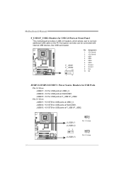
...: +5V for USB ports at F_USB1/F_USB2. JUSBV3: +5V for USB ports at RJ45USB1. JUSBV3: +5V STB for USB ports at Front Panel This motherboard provides 2 USB 2.0 headers, which allows user to connect additional USB cable on the PC front panel, and also can be connected with internal USB devices..., like USB card reader. Motherboard Manual F_USB1/F_USB2: Headers for USB 2.0 Ports at F_USB1/F_USB2. F_ US B1 F_ US B2 2 10 1 9 Pin Assignment 1 +5V (fused) 2 +5V (fused) 3 ...
...: +5V for USB ports at F_USB1/F_USB2. JUSBV3: +5V for USB ports at RJ45USB1. JUSBV3: +5V STB for USB ports at Front Panel This motherboard provides 2 USB 2.0 headers, which allows user to connect additional USB cable on the PC front panel, and also can be connected with internal USB devices..., like USB card reader. Motherboard Manual F_USB1/F_USB2: Headers for USB 2.0 Ports at F_USB1/F_USB2. F_ US B1 F_ US B2 2 10 1 9 Pin Assignment 1 +5V (fused) 2 +5V (fused) 3 ...
Setup Manual
Page 17
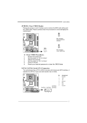
G41U3G JCMOS1: Clear CMOS Header Placing the jumper on the AC. 6. Set the jumper to "Pin 1-2 close ". 3. Pin Assignment 1 Ground 2 TX+ 3 TX4 Ground 5 RX6 RX+ SATA4 7 Ground SATA1 SATA2 SATA3 14 7 15 Reset your desired password or clear the CMOS data. Remove AC power line. 2. SATA1~SATA4: Serial ATA Connectors The motherboard... has a PCI to avoid damaging the motherboard. 1 3 Pin 1-2 Close: Normal Operation (Default). 1 3 1 Pin 2-3 Close: 3 Clear ...
G41U3G JCMOS1: Clear CMOS Header Placing the jumper on the AC. 6. Set the jumper to "Pin 1-2 close ". 3. Pin Assignment 1 Ground 2 TX+ 3 TX4 Ground 5 RX6 RX+ SATA4 7 Ground SATA1 SATA2 SATA3 14 7 15 Reset your desired password or clear the CMOS data. Remove AC power line. 2. SATA1~SATA4: Serial ATA Connectors The motherboard... has a PCI to avoid damaging the motherboard. 1 3 Pin 1-2 Close: Normal Operation (Default). 1 3 1 Pin 2-3 Close: 3 Clear ...
Setup Manual
Page 18
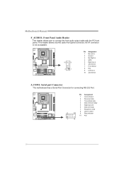
Motherboard Manual F_AUDIO1: Front Panel Audio Header This header allows user to send 2 10 9 Ring indicator 10 Key 1 9 16 This header allows only HD audio front ... in 2 Ground 3 Mic Right in 4 GPIO 5 Right line in 6 Jack Sense 7 Front Sense 8 Key 9 Left line in 10 Jack Sense J_COM1: Serial port Connector The motherboard has a Serial Port Connector for connecting RS-232 Port.
Motherboard Manual F_AUDIO1: Front Panel Audio Header This header allows user to send 2 10 9 Ring indicator 10 Key 1 9 16 This header allows only HD audio front ... in 2 Ground 3 Mic Right in 4 GPIO 5 Right line in 6 Jack Sense 7 Front Sense 8 Key 9 Left line in 10 Jack Sense J_COM1: Serial port Connector The motherboard has a Serial Port Connector for connecting RS-232 Port.
Setup Manual
Page 20
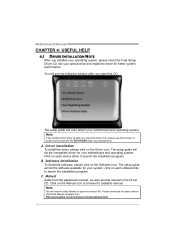
...18 Driver Installation To install the driver, please click on the Software icon. You will need Acrobat Reader to launch the installation program. Motherboard Manual CHAPTER 4: USEFUL HELP 4.1 DRIVER INSTALLATION NOTE After you insert the Driver CD, please use file browser to browse for available manual...Note: You will see the following window after you installed your operating system, please insert the Fully Setup Driver CD into your motherboard and operating system. A. Click on each device driver to open the manual file. The setup guide will list the compatible driver ...
...18 Driver Installation To install the driver, please click on the Software icon. You will need Acrobat Reader to launch the installation program. Motherboard Manual CHAPTER 4: USEFUL HELP 4.1 DRIVER INSTALLATION NOTE After you insert the Driver CD, please use file browser to browse for available manual...Note: You will see the following window after you installed your operating system, please insert the Fully Setup Driver CD into your motherboard and operating system. A. Click on each device driver to open the manual file. The setup guide will list the compatible driver ...
Setup Manual
Page 22
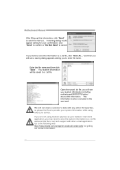
... file, click "Save As..." If you will see a saving dialog appears asking you to the following web http://www.biostar.com.tw/app/en-us/about/contact.php for your system information including motherboard/BIOS/CPU/video/ device/OS information. and then you want to save the system information to a .txt file... eHot-Line service. We will be saved to send the mail out. If you may need to save this information, click "Send" to a .txt file. Motherboard Manual After filling up this information to cancel.
... file, click "Save As..." If you will see a saving dialog appears asking you to the following web http://www.biostar.com.tw/app/en-us/about/contact.php for your system information including motherboard/BIOS/CPU/video/ device/OS information. and then you want to save the system information to a .txt file... eHot-Line service. We will be saved to send the mail out. If you may need to save this information, click "Send" to a .txt file. Motherboard Manual After filling up this information to cancel.
Setup Manual
Page 23
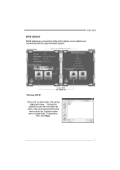
AWARD BIOS Show current BIOS information AMI BIOS Clear CMOS function (Only for AWARD BIOS) Save current BIOS to save file and enter file name. (We recommend that the file name should be English/number and no longer than 7 characters.) Then click Save. 21 Choose the position to a .bin file Update BIOS with a BIOS file Once click on this button, the saving dialog will show. G41U3G BIOS Update BIOS Update is a convenient utility which allows you to update your motherboard BIOS under Windows system.
AWARD BIOS Show current BIOS information AMI BIOS Clear CMOS function (Only for AWARD BIOS) Save current BIOS to save file and enter file name. (We recommend that the file name should be English/number and no longer than 7 characters.) Then click Save. 21 Choose the position to a .bin file Update BIOS with a BIOS file Once click on this button, the saving dialog will show. G41U3G BIOS Update BIOS Update is a convenient utility which allows you to update your motherboard BIOS under Windows system.

Setup Manual
Page 24
... should be changed without notice. In the BIOS setup, use the Load Optimized Defaults function and then Save and Exit Setup to exit BIOS setup. Motherboard Manual Before doing this procedure.
... should be changed without notice. In the BIOS setup, use the Load Optimized Defaults function and then Save and Exit Setup to exit BIOS setup. Motherboard Manual Before doing this procedure.
Setup Manual
Page 25
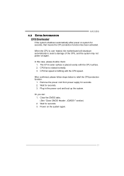
... "Close CMOS Header: JCMOS1" section) 2. When the CPU is fulfilling with the CPU surface. 2. CPU fan speed is over heated, the motherboard will shutdown automatically to relief the CPU protection function. 1. After confirmed, please follow steps below to avoid a damage of the CPU, and the...system may not power on system for seconds. 3. Or you can: 1. The CPU cooler surface is rotated normally. 3. Wait for seconds. 2. G41U3G 4.3 EXTRA INFORMATION CPU Overheated If the system shutdown automatically after power on again. In this case, please double check: 1. CPU fan is placed...
... "Close CMOS Header: JCMOS1" section) 2. When the CPU is fulfilling with the CPU surface. 2. CPU fan speed is over heated, the motherboard will shutdown automatically to relief the CPU protection function. 1. After confirmed, please follow steps below to avoid a damage of the CPU, and the...system may not power on system for seconds. 3. Or you can: 1. The CPU cooler surface is rotated normally. 3. Wait for seconds. 2. G41U3G 4.3 EXTRA INFORMATION CPU Overheated If the system shutdown automatically after power on again. In this case, please double check: 1. CPU fan is placed...

