
Setup Manual
Page 3
...make sure you follow the instructions below: „ Prepare a dry and stable working environment with sufficient lighting. „ Always disconnect the computer from power outlet before operation. „ Before you for ATX Case X 1 Installation Guide X 1 Fully Setup Driver CD X 1 (full version manual ...remove the static charge. „ Avoid touching the components on motherboard or the rear side of the board unless necessary. CHAPTER 1: INTRODUCTION G41D3C 1.1 BEFORE YOU START Thank you take the motherboard out from dangerous area, such as heat source, humid air and water. 1.2 PACKAGE ...
...make sure you follow the instructions below: „ Prepare a dry and stable working environment with sufficient lighting. „ Always disconnect the computer from power outlet before operation. „ Before you for ATX Case X 1 Installation Guide X 1 Fully Setup Driver CD X 1 (full version manual ...remove the static charge. „ Avoid touching the components on motherboard or the rear side of the board unless necessary. CHAPTER 1: INTRODUCTION G41D3C 1.1 BEFORE YOU START Thank you take the motherboard out from dangerous area, such as heat source, humid air and water. 1.2 PACKAGE ...
Setup Manual
Page 5
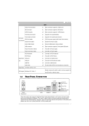
...Biostar reserves the right to the audio port, please use the Line In (blue) and Mic In (Pink) audio jack. 3 Printer Port Connector IDE Connector SATA Connector Front Panel Connector Front Audio Connector On Board CPU Fan header Connectors System Fan header Clear CMOS header USB connector Power Connector (24pin) Power... Connector (4pin) PS/2 Keyboard PS/2 Mouse Back Panel VGA port I/O LAN port USB Port Audio Jack Board Size 170 (W) x 225 (L) mm OS Support Windows XP / Vista / 7 G41D3C SPEC x1 Each connector ...
...Biostar reserves the right to the audio port, please use the Line In (blue) and Mic In (Pink) audio jack. 3 Printer Port Connector IDE Connector SATA Connector Front Panel Connector Front Audio Connector On Board CPU Fan header Connectors System Fan header Clear CMOS header USB connector Power Connector (24pin) Power... Connector (4pin) PS/2 Keyboard PS/2 Mouse Back Panel VGA port I/O LAN port USB Port Audio Jack Board Size 170 (W) x 225 (L) mm OS Support Windows XP / Vista / 7 G41D3C SPEC x1 Each connector ...
Setup Manual
Page 8
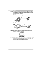
Connect the CPU FAN power cable into the CPU_FAN1. This completes the installation. 6 The CPU will fit only in the correct orientation. Motherboard Manual Step 2: Look for the triangular cut edge. Step 2-1: Step 2-2: Step 3: Hold the CPU down firmly, and then lower the lever to locked position to complete the installation. Step 4: Put the CPU Fan and heatsink assembly on the CPU and buckle it on CPU should point forwards this triangular cut edge on socket, and the golden dot on the retention frame.
Connect the CPU FAN power cable into the CPU_FAN1. This completes the installation. 6 The CPU will fit only in the correct orientation. Motherboard Manual Step 2: Look for the triangular cut edge. Step 2-1: Step 2-2: Step 3: Hold the CPU down firmly, and then lower the lever to locked position to complete the installation. Step 4: Put the CPU Fan and heatsink assembly on the CPU and buckle it on CPU should point forwards this triangular cut edge on socket, and the golden dot on the retention frame.
Setup Manual
Page 9
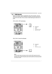
G41D3C 2.2 FAN HEADERS These fan headers support cooling-fans built in the computer. When connecting with wires onto connectors, please note that the red wire is ... be connected to pin#1. Connect the fan cable to the connector while matching the black wire to GND. 7 CPU_FAN1: CPU Fan Header 4 1 Pin Assignment 1 Ground 2 Power 3 FAN RPM rate sense 4 Smart Fan Control SYS_FAN1: System Fan Header Pin Assignment 1 Ground 2 +12V 3 FAN RPM rate sense 13 Note: The CPU_FAN1 support 4-pin...
G41D3C 2.2 FAN HEADERS These fan headers support cooling-fans built in the computer. When connecting with wires onto connectors, please note that the red wire is ... be connected to pin#1. Connect the fan cable to the connector while matching the black wire to GND. 7 CPU_FAN1: CPU Fan Header 4 1 Pin Assignment 1 Ground 2 Power 3 FAN RPM rate sense 4 Smart Fan Control SYS_FAN1: System Fan Header Pin Assignment 1 Ground 2 +12V 3 FAN RPM rate sense 13 Note: The CPU_FAN1 support 4-pin...
Setup Manual
Page 13
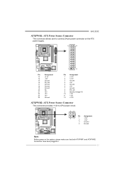
G41D3C ATXPWR1: ATX Power Source Connector This connector allows user to connect 24-pin power connector on the ATX power supply. 12 24 1 13 Pin Assignment 13 +3.3V 14 -12V 15 Ground 16 PS_ON 17 Ground 18 Ground 19 Ground 20 NC ... 6 +5V 7 Ground 8 PW_OK 9 Standby Voltage+5V 10 +12V 11 +12V 12 +3.3V ATXPWR2: ATX Power Source Connector This connector provides +12V to CPU power circuit. 32 Pin Assignment 4 1 1 +12V 2 +12V 3 Ground 4 Ground Note: Before power on the system, please make sure that both ATXPWR1 and ATXPWR2 connectors have been plugged-in...
G41D3C ATXPWR1: ATX Power Source Connector This connector allows user to connect 24-pin power connector on the ATX power supply. 12 24 1 13 Pin Assignment 13 +3.3V 14 -12V 15 Ground 16 PS_ON 17 Ground 18 Ground 19 Ground 20 NC ... 6 +5V 7 Ground 8 PW_OK 9 Standby Voltage+5V 10 +12V 11 +12V 12 +3.3V ATXPWR2: ATX Power Source Connector This connector provides +12V to CPU power circuit. 32 Pin Assignment 4 1 1 +12V 2 +12V 3 Ground 4 Ground Note: Before power on the system, please make sure that both ATXPWR1 and ATXPWR2 connectors have been plugged-in...
Setup Manual
Page 15
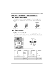
...closed 3.2 DETAIL SETTINGS Pin1-2 closed PANEL1: Front Panel Header This 16-pin connector includes Power-on pins, the jumper is "close", if not, that means the jumper is placed on , Reset, HDD LED, Power LED, and speaker connection. When the jumper cap is "open". It allows user to ...set up jumpers. G41D3C CHAPTER 3: HEADERS & JUMPERS SETUP 3.1 HOW TO SETUP JUMPERS The illustration shows how to connect the...
...closed 3.2 DETAIL SETTINGS Pin1-2 closed PANEL1: Front Panel Header This 16-pin connector includes Power-on pins, the jumper is "close", if not, that means the jumper is placed on , Reset, HDD LED, Power LED, and speaker connection. When the jumper cap is "open". It allows user to ...set up jumpers. G41D3C CHAPTER 3: HEADERS & JUMPERS SETUP 3.1 HOW TO SETUP JUMPERS The illustration shows how to connect the...
Setup Manual
Page 16
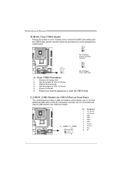
... the motherboard. 3 1 Pin 1-2 Close: Normal Operation (Default). 3 1 3 Pin 2-3 Close: 1 Clear CMOS data. ※ Clear CMOS Procedures: 1. F_USB1/F_USB2: Headers for five seconds. 4. Remove AC power line. 2. Power on the PC front panel, and also can be connected with internal USB devices, like USB card reader. Set the jumper to connect additional USB...
... the motherboard. 3 1 Pin 1-2 Close: Normal Operation (Default). 3 1 3 Pin 2-3 Close: 1 Clear CMOS data. ※ Clear CMOS Procedures: 1. F_USB1/F_USB2: Headers for five seconds. 4. Remove AC power line. 2. Power on the PC front panel, and also can be connected with internal USB devices, like USB card reader. Set the jumper to connect additional USB...
Setup Manual
Page 19
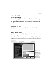
... is useful for analyzing the problem you may not be collected in forma tion to the optical drive. Exi t thi s dialog. 4.2 SOFTWARE G41D3C Installing Software 1. This utility will show the i nformation which is a convenient utility that helps you to help you . Provide the e-ma il... of the memor y module manufacturer. The drivers installation program would like to send the copy to. *Provid e the name of the power suppl y manufacturer and the model no. Wi thout this utility,please set Outlook Express as your default e-mail clientapplication program. *represents important...
... is useful for analyzing the problem you may not be collected in forma tion to the optical drive. Exi t thi s dialog. 4.2 SOFTWARE G41D3C Installing Software 1. This utility will show the i nformation which is a convenient utility that helps you to help you . Provide the e-ma il... of the memor y module manufacturer. The drivers installation program would like to send the copy to. *Provid e the name of the power suppl y manufacturer and the model no. Wi thout this utility,please set Outlook Express as your default e-mail clientapplication program. *represents important...
Setup Manual
Page 24
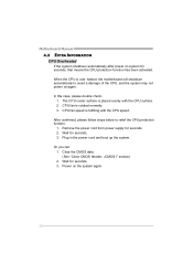
... will shutdown automatically to relief the CPU protection function. 1. Wait for seconds. 3. CPU fan speed is rotated normally. 3. Remove the power cord from power supply for seconds, that means the CPU protection function has been activated. After confirmed, please follow steps below to avoid a damage of ...the CPU, and the system may not power on the system again. 22 Plug in the power cord and boot up the system. Power on again. Or you can: 1. Motherboard Manual 4.3 EXTRA INFORMATION CPU Overheated If the system shutdown...
... will shutdown automatically to relief the CPU protection function. 1. Wait for seconds. 3. CPU fan speed is rotated normally. 3. Remove the power cord from power supply for seconds, that means the CPU protection function has been activated. After confirmed, please follow steps below to avoid a damage of ...the CPU, and the system may not power on the system again. 22 Plug in the power cord and boot up the system. Power on again. Or you can: 1. Motherboard Manual 4.3 EXTRA INFORMATION CPU Overheated If the system shutdown...
Setup Manual
Page 25
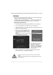
... for the motherboard. 2. Select the proper BIOS file and press then to proceed. z This utility only allows storage device with BIO-Flasher 1. Power on the right appears. Updating BIOS with FAT32/16 format and single partition. Press to perform the BIOS update process. 6. Select the device contains... press to reboot the system. After the update process, the utility will ask you an easy and simple way to system boot failure. 23 G41D3C BIO-Flasher BIO-Flasher is built in the BIOS chip. The BIO-Flasher is a BIOS flashing utility providing you to enter the utility. 5....
... for the motherboard. 2. Select the proper BIOS file and press then to proceed. z This utility only allows storage device with BIO-Flasher 1. Power on the right appears. Updating BIOS with FAT32/16 format and single partition. Press to perform the BIOS update process. 6. Select the device contains... press to reboot the system. After the update process, the utility will ask you an easy and simple way to system boot failure. 23 G41D3C BIO-Flasher BIO-Flasher is built in the BIOS chip. The BIO-Flasher is a BIOS flashing utility providing you to enter the utility. 5....
Setup Manual
Page 27
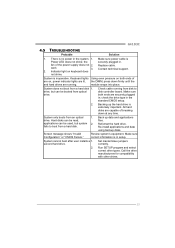
... 1. fan of are running from a hard disk 1. System is Power LED does not shine; Backing up data and applications files. Hard disks... manufacturers for compatibility with other drives. 25 Indicator light on , power indicator lights are lit, the DIMM, press down at any time...on keyboard does not shine. Make sure both ends of the power supply does not 2. Reformat the hard drive. Contact technical ... applications and data using backup disks. Make sure correct information is no power in setup. Set master/slave jumpers correctly. drive, but system 2. Screen...
... 1. fan of are running from a hard disk 1. System is Power LED does not shine; Backing up data and applications files. Hard disks... manufacturers for compatibility with other drives. 25 Indicator light on , power indicator lights are lit, the DIMM, press down at any time...on keyboard does not shine. Make sure both ends of the power supply does not 2. Reformat the hard drive. Contact technical ... applications and data using backup disks. Make sure correct information is no power in setup. Set master/slave jumpers correctly. drive, but system 2. Screen...
Bios Setup
Page 2
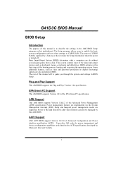
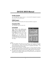
G41D3C BIOS Manual BIOS Setup Introduction The purpose of this manual will to guide you through the options and settings in BIOS Setup. The rest of .... Plug and Play Support This AMI BIOS supports the Plug and Play Version 1.0A specification. Sleep and Suspend power management modes are implemented via the System Management Interrupt (SMI). Power to CMOS RAM. The power of the EPA Green PC specification. Some additional features, such as keyboard, mouse, serial ports and disk drives...
G41D3C BIOS Manual BIOS Setup Introduction The purpose of this manual will to guide you through the options and settings in BIOS Setup. The rest of .... Plug and Play Support This AMI BIOS supports the Plug and Play Version 1.0A specification. Sleep and Suspend power management modes are implemented via the System Management Interrupt (SMI). Power to CMOS RAM. The power of the EPA Green PC specification. Some additional features, such as keyboard, mouse, serial ports and disk drives...
Bios Setup
Page 3
Using Setup When starting up the computer, press during the Power-On Self-Test (POST) to select item and change the settings. General Help Navigation Keys Notice z The default BIOS settings apply for any mistakes found ... utility, you can use these keys to enter the BIOS setup utility. The actual BIOS information and settings on board may be changed without notice. G41D3C BIOS Manual PCI Bus Support This AMI BIOS also supports Version 2.3 of this manual is supported. Use Load Setup Default under the Exit Menu. z For...
Using Setup When starting up the computer, press during the Power-On Self-Test (POST) to select item and change the settings. General Help Navigation Keys Notice z The default BIOS settings apply for any mistakes found ... utility, you can use these keys to enter the BIOS setup utility. The actual BIOS information and settings on board may be changed without notice. G41D3C BIOS Manual PCI Bus Support This AMI BIOS also supports Version 2.3 of this manual is supported. Use Load Setup Default under the Exit Menu. z For...
Bios Setup
Page 8
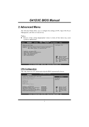
...Advanced BIOS SETUP UTILITY PCIPnP Boot Chipset Performance Exit Advanced Settings WARNING: Setting wrong values in items of CPU, Super I/O, Power Management, and other system devices. Advanced BIOS SETUP UTILITY Configure advanced CPU settings Module Version:xx.xx Manufacturer:Intel Frequency : ... Tech [Enabled] Execute-Disable Bit Capability [Enabled] Core Multi-Processing [Enabled] Options Disabled Enabled Select Screen Select Item +- G41D3C BIOS Manual 2 Advanced Menu The Advanced Menu allows you to configure the settings of this menu may cause system to Sub ...
...Advanced BIOS SETUP UTILITY PCIPnP Boot Chipset Performance Exit Advanced Settings WARNING: Setting wrong values in items of CPU, Super I/O, Power Management, and other system devices. Advanced BIOS SETUP UTILITY Configure advanced CPU settings Module Version:xx.xx Manufacturer:Intel Frequency : ... Tech [Enabled] Execute-Disable Bit Capability [Enabled] Core Multi-Processing [Enabled] Options Disabled Enabled Select Screen Select Item +- G41D3C BIOS Manual 2 Advanced Menu The Advanced Menu allows you to configure the settings of this menu may cause system to Sub ...
Bios Setup
Page 9
... buffer overflow attacks. This determines the kind of basic information CPUID can do so, it as well. G41D3C BIOS Manual C1E Support C1E is "Enhanced Halt State" function, this function helps to save power and decrease heat by making the next cache line immediately available if the processor requires it must first...
... buffer overflow attacks. This determines the kind of basic information CPUID can do so, it as well. G41D3C BIOS Manual C1E Support C1E is "Enhanced Halt State" function, this function helps to save power and decrease heat by making the next cache line immediately available if the processor requires it must first...
Bios Setup
Page 10
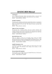
G41D3C BIOS Manual Core Multi-Processing This item allows multi-processing function for multi-core processors. Options: Normal (Default) Using Parallel port as Extended Capabilities Port. ... Advanced BIOS SETUP UTILITY Configure ITE8728 Super IO Chipset Parallel Port Address Parallel Port Mode Parallel Port IRQ Keyboard PowerOn Mouse PowerOn Restore on AC Power Loss [378] [Normal] [IRQ7] [Disabled] [Disabled] [Power Off] Allows BIOS to determine how the parallel port should function.
G41D3C BIOS Manual Core Multi-Processing This item allows multi-processing function for multi-core processors. Options: Normal (Default) Using Parallel port as Extended Capabilities Port. ... Advanced BIOS SETUP UTILITY Configure ITE8728 Super IO Chipset Parallel Port Address Parallel Port Mode Parallel Port IRQ Keyboard PowerOn Mouse PowerOn Restore on AC Power Loss [378] [Normal] [IRQ7] [Disabled] [Disabled] [Power Off] Allows BIOS to determine how the parallel port should function.

Bios Setup
Page 11
G41D3C BIOS Manual Parallel Port IRQ This item allows you to control the keyboard power on function. Options: IRQ7 (Default) / IRQ5 / Disabled Keyboard PowerOn This item allows you to the status before power failure or interrupt occurs. Options: Ctrl+F1 (Default) / Wake Key / Power Key / Ctrl+... when Keyboard PowerOn is set "Specific Key." Choosing Enabled will show only when Keyboard PowerOn is set "Stroke Key." Options: Power Off (Default) / Power ON / Last State 10 Options: Disabled (Default) / Enabled Restore on function. Options: Disabled (Default) / Specific Key ...
G41D3C BIOS Manual Parallel Port IRQ This item allows you to control the keyboard power on function. Options: IRQ7 (Default) / IRQ5 / Disabled Keyboard PowerOn This item allows you to the status before power failure or interrupt occurs. Options: Ctrl+F1 (Default) / Wake Key / Power Key / Ctrl+... when Keyboard PowerOn is set "Specific Key." Choosing Enabled will show only when Keyboard PowerOn is set "Stroke Key." Options: Power Off (Default) / Power ON / Last State 10 Options: Disabled (Default) / Enabled Restore on function. Options: Disabled (Default) / Specific Key ...
Bios Setup
Page 14
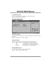
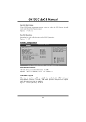
...used to the set value, the CPU/System fan will raise the speed of ACPI. Options: Enabled (Default) / Disabled 13 G41D3C BIOS Manual Fan Ctrl Start Value When CPU/System temperature arrives to enable or disable the motherboard's APIC (Advanced Programmable Interrupt Controller...). The APIC provides multiprocessor support, more IRQs and faster interrupt handling. Different ACPI verison has some addition. Options: 1~127 Power Configuration Advanced BIOS SETUP UTILITY ACPI Settings ACPI Version Features ACPI APIC support AMI OEMB table Headless mode Energy Lake Feature APIC ...
...used to the set value, the CPU/System fan will raise the speed of ACPI. Options: Enabled (Default) / Disabled 13 G41D3C BIOS Manual Fan Ctrl Start Value When CPU/System temperature arrives to enable or disable the motherboard's APIC (Advanced Programmable Interrupt Controller...). The APIC provides multiprocessor support, more IRQs and faster interrupt handling. Different ACPI verison has some addition. Options: 1~127 Power Configuration Advanced BIOS SETUP UTILITY ACPI Settings ACPI Version Features ACPI APIC support AMI OEMB table Headless mode Energy Lake Feature APIC ...
Bios Setup
Page 21
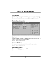
.../disable Full Screen LOGO Show function. Change Option F1 General Help F10 Save and Exit ESC Exit vxx.xx (C)Copyright 1985-200x, American Megatrends, Inc. G41D3C BIOS Manual CD/DVD Drives The BIOS will decrease the time needed to boot the system. This will attempt to arrange the CD/DVD drive... boot sequence automatically. The number of device items that appears on the screen depends on the number of the Power On Self-Test (POST) to execute after you to skip certain tests while booting. Quick Boot Enabling this option will cause an abridged version of...
.../disable Full Screen LOGO Show function. Change Option F1 General Help F10 Save and Exit ESC Exit vxx.xx (C)Copyright 1985-200x, American Megatrends, Inc. G41D3C BIOS Manual CD/DVD Drives The BIOS will decrease the time needed to boot the system. This will attempt to arrange the CD/DVD drive... boot sequence automatically. The number of device items that appears on the screen depends on the number of the Power On Self-Test (POST) to execute after you to skip certain tests while booting. Quick Boot Enabling this option will cause an abridged version of...
Bios Setup
Page 28
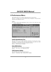
... ESC Exit vxx.xx (C)Copyright 1985-200x, American Megatrends, Inc. Options: x11.5 / x6.0 ~ x11.0 (Differed by software. Max= 600MHz 27 Options: 266 (Default) / Min= 100MHz; G41D3C BIOS Manual 6 Performance Menu This submenu allows you to change voltage and clock of various devices. (However, we suggest you to select the CPU Frequency... is a technology built into some Intel processors that setting inappropriate values in items of this menu may cause system to enable SpeedStep technology for better power saving.
... ESC Exit vxx.xx (C)Copyright 1985-200x, American Megatrends, Inc. Options: x11.5 / x6.0 ~ x11.0 (Differed by software. Max= 600MHz 27 Options: 266 (Default) / Min= 100MHz; G41D3C BIOS Manual 6 Performance Menu This submenu allows you to change voltage and clock of various devices. (However, we suggest you to select the CPU Frequency... is a technology built into some Intel processors that setting inappropriate values in items of this menu may cause system to enable SpeedStep technology for better power saving.


