
Setup Manual
Page 2
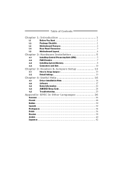
Table of Contents Chapter 1: Introduction 1 1.1 Before You Start 1 1.2 Package Checklist 1 1.3 Motherboard Features 2 1.4 Rear Panel Connectors 3 1.5 Motherboard Layout 4 Chapter 2: Hardware Installation 5 2.1 Installing Central Processing Unit (CPU 5 2.2 FAN Headers 7 2.3 Installing System Memory 8 2.4 Connectors and Slots 10 Chapter 3: Headers & Jumpers Setup 13 3.1 How to ...
Table of Contents Chapter 1: Introduction 1 1.1 Before You Start 1 1.2 Package Checklist 1 1.3 Motherboard Features 2 1.4 Rear Panel Connectors 3 1.5 Motherboard Layout 4 Chapter 2: Hardware Installation 5 2.1 Installing Central Processing Unit (CPU 5 2.2 FAN Headers 7 2.3 Installing System Memory 8 2.4 Connectors and Slots 10 Chapter 3: Headers & Jumpers Setup 13 3.1 How to ...
Setup Manual
Page 3
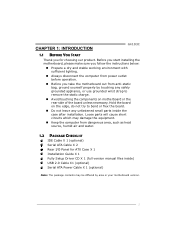
CHAPTER 1: INTRODUCTION G41D3C 1.1 BEFORE YOU START Thank you take the motherboard out from anti-static bag, ground yourself properly by touching any safely grounded appliance, or use grounded wrist strap to remove the static charge. „... version manual files inside the case after installation. Loose parts will cause short circuits which may be differed by area or your motherboard version. 1 Before you start installing the motherboard, please make sure you follow the instructions below: „ Prepare a dry and stable working environment with sufficient lighting. „ Always ...
CHAPTER 1: INTRODUCTION G41D3C 1.1 BEFORE YOU START Thank you take the motherboard out from anti-static bag, ground yourself properly by touching any safely grounded appliance, or use grounded wrist strap to remove the static charge. „... version manual files inside the case after installation. Loose parts will cause short circuits which may be differed by area or your motherboard version. 1 Before you start installing the motherboard, please make sure you follow the instructions below: „ Prepare a dry and stable working environment with sufficient lighting. „ Always ...
Setup Manual
Page 4
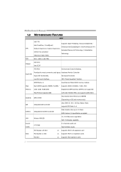
... IDE Controller Ultra DMA 33 / 66 / 100 Bus Master Mode supports PIO Mode 0~4 SATA II Integrated Serial ATA Controller Data transfer rates up to 3.0 Gb/s. Motherboard Manual 1.3 MOTHERBOARD FEATURES SPEC LGA 775 Supports Hyper-Threading / Execute Disable Bit / Intel Core2Duo / Core2Quad / Enhanced Intel SpeedStep® / Intel Architecture-64 / CPU Pentium Dual-Core...
... IDE Controller Ultra DMA 33 / 66 / 100 Bus Master Mode supports PIO Mode 0~4 SATA II Integrated Serial ATA Controller Data transfer rates up to 3.0 Gb/s. Motherboard Manual 1.3 MOTHERBOARD FEATURES SPEC LGA 775 Supports Hyper-Threading / Execute Disable Bit / Intel Core2Duo / Core2Quad / Enhanced Intel SpeedStep® / Intel Architecture-64 / CPU Pentium Dual-Core...
Setup Manual
Page 6
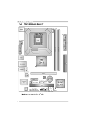
Motherboard Manual 1.5 MOTHERBOARD LAYOUT KBMS1 LGA775 ATX PW R2 CPU1 CPU _FA N1 ATX PW R1 D DR3_A 1 D DR3_B 1 VG A1 ID E1 USB1 RJ 45U SB 1 Intel G41 AU DIO1 F _AU DI O1 LAN Super I/O PEX16_1 PEX1_1 SYS_FAN1 BIOS BAT1 F_USB2 F_USB1 PCI1 Intel ICH7 SATA1 Codec J_PR INT 1 PAN EL1 JC MOS1 SATA2 Note: ■ represents the 1st pin. 4
Motherboard Manual 1.5 MOTHERBOARD LAYOUT KBMS1 LGA775 ATX PW R2 CPU1 CPU _FA N1 ATX PW R1 D DR3_A 1 D DR3_B 1 VG A1 ID E1 USB1 RJ 45U SB 1 Intel G41 AU DIO1 F _AU DI O1 LAN Super I/O PEX16_1 PEX1_1 SYS_FAN1 BIOS BAT1 F_USB2 F_USB1 PCI1 Intel ICH7 SATA1 Codec J_PR INT 1 PAN EL1 JC MOS1 SATA2 Note: ■ represents the 1st pin. 4
Setup Manual
Page 8
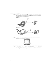
Step 2-1: Step 2-2: Step 3: Hold the CPU down firmly, and then lower the lever to locked position to complete the installation. Step 4: Put the CPU Fan and heatsink assembly on the CPU and buckle it on CPU should point forwards this triangular cut edge on socket, and the golden dot on the retention frame. Connect the CPU FAN power cable into the CPU_FAN1. This completes the installation. 6 The CPU will fit only in the correct orientation. Motherboard Manual Step 2: Look for the triangular cut edge.
Step 2-1: Step 2-2: Step 3: Hold the CPU down firmly, and then lower the lever to locked position to complete the installation. Step 4: Put the CPU Fan and heatsink assembly on the CPU and buckle it on CPU should point forwards this triangular cut edge on socket, and the golden dot on the retention frame. Connect the CPU FAN power cable into the CPU_FAN1. This completes the installation. 6 The CPU will fit only in the correct orientation. Motherboard Manual Step 2: Look for the triangular cut edge.
Setup Manual
Page 10
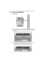
DDR3 module 1. Align a DIMM on the slot so that the notch on the DIMM matches the break on the Slot. 2. Insert the DIMM vertically and firmly into the slot until the retaining chip snap back in place and the DIMM is properly seated. 8 Unlock a DIMM slot by pressing the retaining clips outward. D DR 3 _A1 D DR 3 _B1 Motherboard Manual 2.3 INSTALLING SYSTEM MEMORY A.
DDR3 module 1. Align a DIMM on the slot so that the notch on the DIMM matches the break on the Slot. 2. Insert the DIMM vertically and firmly into the slot until the retaining chip snap back in place and the DIMM is properly seated. 8 Unlock a DIMM slot by pressing the retaining clips outward. D DR 3 _A1 D DR 3 _B1 Motherboard Manual 2.3 INSTALLING SYSTEM MEMORY A.
Setup Manual
Page 12
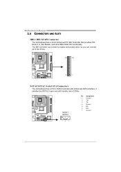
The IDE connector can connect a master and a slave drive, so you can connect up to two drives. 40 39 2 1 SATA1/SATA2: Serial ATA Connectors The motherboard has a PCI to SATA Controller with 2channels SATA interface, it satisfies the SATA 2.0 spec and with transfer rate of 3Gb/s. Motherboard Manual 2.4 CONNECTORS AND SLOTS IDE1: IDE/ATAPI Connector The motherboard has a 32-bit Enhanced PCI IDE Controller that provides PIO Mode 0~4, Bus Master, and Ultra DMA 33/66/100 functionality. SATA 1 SATA 2 Pin Assignment 1 Ground 2 TX+ 3 TX4 Ground 5 RX6 RX+ 7 Ground 14 7 10
The IDE connector can connect a master and a slave drive, so you can connect up to two drives. 40 39 2 1 SATA1/SATA2: Serial ATA Connectors The motherboard has a PCI to SATA Controller with 2channels SATA interface, it satisfies the SATA 2.0 spec and with transfer rate of 3Gb/s. Motherboard Manual 2.4 CONNECTORS AND SLOTS IDE1: IDE/ATAPI Connector The motherboard has a 32-bit Enhanced PCI IDE Controller that provides PIO Mode 0~4, Bus Master, and Ultra DMA 33/66/100 functionality. SATA 1 SATA 2 Pin Assignment 1 Ground 2 TX+ 3 TX4 Ground 5 RX6 RX+ 7 Ground 14 7 10
Setup Manual
Page 14
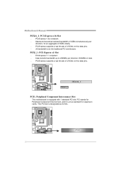
...Express 1.1 compliant. - Data transfer bandwidth up to 250MB/s per direction, for expansion cards. PEX16_1 PEX1_1 PCI1: Peripheral Component Interconnect Slot This motherboard is designated as 32 bits. PCI-Express supports a raw bit-rate of 4GB/s simultaneously per direction; 500MB/s in total. - PCI-Express ...supports a raw bit-rate of 8GB/s totally. - PCI1 12 PEX1_1: PCI-Express x1 Slot - Motherboard Manual PEX16_1: PCI-Express x16 Slot - PCI stands for Peripheral Component Interconnect, and it is a bus standard for an aggregate of 2.5Gb/s ...
...Express 1.1 compliant. - Data transfer bandwidth up to 250MB/s per direction, for expansion cards. PEX16_1 PEX1_1 PCI1: Peripheral Component Interconnect Slot This motherboard is designated as 32 bits. PCI-Express supports a raw bit-rate of 4GB/s simultaneously per direction; 500MB/s in total. - PCI-Express ...supports a raw bit-rate of 8GB/s totally. - PCI1 12 PEX1_1: PCI-Express x1 Slot - Motherboard Manual PEX16_1: PCI-Express x16 Slot - PCI stands for Peripheral Component Interconnect, and it is a bus standard for an aggregate of 2.5Gb/s ...
Setup Manual
Page 16
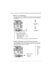
...USB5 USB+ 6 USB+ 7 Ground 8 Ground 9 Key 10 NC 14 Wait for USB 2.0 Ports at Front Panel This motherboard provides 2 USB 2.0 headers, which allows user to "Pin 1-2 close ". 3. Set the jumper to avoid damaging the motherboard. 3 1 Pin 1-2 Close: Normal Operation (Default). 3 1 3 Pin 2-3 Close: 1 Clear CMOS data. ※ ...Clear CMOS Procedures: 1. Power on the AC. 6. Motherboard Manual JCMOS1: Clear CMOS Header Placing the jumper on pin2-3 allows user to restore the BIOS safe setting and the CMOS data, please ...
...USB5 USB+ 6 USB+ 7 Ground 8 Ground 9 Key 10 NC 14 Wait for USB 2.0 Ports at Front Panel This motherboard provides 2 USB 2.0 headers, which allows user to "Pin 1-2 close ". 3. Set the jumper to avoid damaging the motherboard. 3 1 Pin 1-2 Close: Normal Operation (Default). 3 1 3 Pin 2-3 Close: 1 Clear CMOS data. ※ ...Clear CMOS Procedures: 1. Power on the AC. 6. Motherboard Manual JCMOS1: Clear CMOS Header Placing the jumper on pin2-3 allows user to restore the BIOS safe setting and the CMOS data, please ...
Setup Manual
Page 18
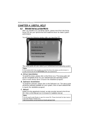
... guide will need Acrobat Reader to open the manual file. The setup guide will list the compatible driver for your motherboard and operating system. Motherboard Manual CHAPTER 4: USEFUL HELP 4.1 DRIVER INSTALLATION NOTE After you installed your operating system, please insert the Fully Setup... Driver Installation To install the driver, please click on the Software icon. The setup guide will list the software available for your motherboard and operating system. Click on the Manual icon to launch the installation program. A. Click on each device driver to browse for ...
... guide will need Acrobat Reader to open the manual file. The setup guide will list the compatible driver for your motherboard and operating system. Motherboard Manual CHAPTER 4: USEFUL HELP 4.1 DRIVER INSTALLATION NOTE After you installed your operating system, please insert the Fully Setup... Driver Installation To install the driver, please click on the Software icon. The setup guide will list the software available for your motherboard and operating system. Click on the Manual icon to launch the installation program. A. Click on each device driver to browse for ...
Setup Manual
Page 20
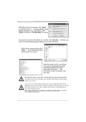
... .txt file, you may need to save this information, click "Send" to the following web http://www.biostar.com.tw/app/en-us/about/contact.php for your system information including motherboard/BIOS/CPU/video/ device/OS information. If you are not using Outlook Express as your default e-mail client ...name and then click "Save". We will see a saving dialog appears asking you will be saved to cancel. Go to send the mail out. Motherboard Manual After filling up this information to enter file name. A warning dialog would appear asking for getting our contact information. 18
... .txt file, you may need to save this information, click "Send" to the following web http://www.biostar.com.tw/app/en-us/about/contact.php for your system information including motherboard/BIOS/CPU/video/ device/OS information. If you are not using Outlook Express as your default e-mail client ...name and then click "Save". We will see a saving dialog appears asking you will be saved to cancel. Go to send the mail out. Motherboard Manual After filling up this information to enter file name. A warning dialog would appear asking for getting our contact information. 18
Setup Manual
Page 21
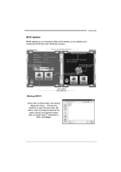
Choose the position to a .bin file Update BIOS with a BIOS file Once click on this button, the saving dialog will show. AWARD BIOS Show current BIOS information AMI BIOS Clear CMOS function (Only for AWARD BIOS) Online Update function (Only for AMI BIOS) Save current BIOS to save file and enter file name. (We recommend that the file name should be English/number and no longer than 7 characters.) Then click Save. 19 G41D3C BIOS Update BIOS Update is a convenient utility which allows you to update your motherboard BIOS under Windows system.
Choose the position to a .bin file Update BIOS with a BIOS file Once click on this button, the saving dialog will show. AWARD BIOS Show current BIOS information AMI BIOS Clear CMOS function (Only for AWARD BIOS) Online Update function (Only for AMI BIOS) Save current BIOS to save file and enter file name. (We recommend that the file name should be English/number and no longer than 7 characters.) Then click Save. 19 G41D3C BIOS Update BIOS Update is a convenient utility which allows you to update your motherboard BIOS under Windows system.
Setup Manual
Page 22
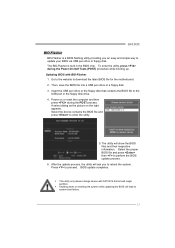
... , please download the proper BIOS file from the website. After the BIOS Backup procedure, the open any other applications during this process may take minutes. Motherboard Manual Before doing this procedure. While the system boots up and the full screen logo shows, press key to exit BIOS setup.
... , please download the proper BIOS file from the website. After the BIOS Backup procedure, the open any other applications during this process may take minutes. Motherboard Manual Before doing this procedure. While the system boots up and the full screen logo shows, press key to exit BIOS setup.
Setup Manual
Page 24
.... 2. Wait for seconds, that means the CPU protection function has been activated. The CPU cooler surface is over heated, the motherboard will shutdown automatically to relief the CPU protection function. 1. Motherboard Manual 4.3 EXTRA INFORMATION CPU Overheated If the system shutdown automatically after power on again. Power on the system again. 22 Clear...
.... 2. Wait for seconds, that means the CPU protection function has been activated. The CPU cooler surface is over heated, the motherboard will shutdown automatically to relief the CPU protection function. 1. Motherboard Manual 4.3 EXTRA INFORMATION CPU Overheated If the system shutdown automatically after power on again. Power on the system again. 22 Clear...
Setup Manual
Page 25
...the computer and then press during the Power-On Self Tests (POST) procedure while booting up. Press to download the latest BIOS file for the motherboard. 2. BIOS update completes. Select the device contains the BIOS file and press to perform the BIOS update process. 6. Then, save the BIOS ...pen drive or floppy disk. z This utility only allows storage device with BIO-Flasher 1. Updating BIOS with FAT32/16 format and single partition. G41D3C BIO-Flasher BIO-Flasher is built in the BIOS chip. To enter the utility, press during the POST process. After the update process, ...
...the computer and then press during the Power-On Self Tests (POST) procedure while booting up. Press to download the latest BIOS file for the motherboard. 2. BIOS update completes. Select the device contains the BIOS file and press to perform the BIOS update process. 6. Then, save the BIOS ...pen drive or floppy disk. z This utility only allows storage device with BIO-Flasher 1. Updating BIOS with FAT32/16 format and single partition. G41D3C BIO-Flasher BIO-Flasher is built in the BIOS chip. To enter the utility, press during the POST process. After the update process, ...
Setup Manual
Page 26
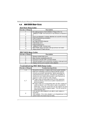
...z If beep codes are generated when all other expansion 6, 7 cards are absent, consult your system manufacturer. Before declaring the motherboard beyond all expansion cards except the video adapter. This will reveal the malfunctioning card. Insert the cards back into the system one ...of the add-in cards is an add-in card, replace or 8 reseat the video adapter. Motherboard Manual 4.4 AMI BIOS BEEP CODE Boot Block Beep Codes Number of Beeps Description 1 No media present. (Insert diskette in floppy drive A:) 2 "AMIBOOT....
...z If beep codes are generated when all other expansion 6, 7 cards are absent, consult your system manufacturer. Before declaring the motherboard beyond all expansion cards except the video adapter. This will reveal the malfunctioning card. Insert the cards back into the system one ...of the add-in cards is an add-in card, replace or 8 reseat the video adapter. Motherboard Manual 4.4 AMI BIOS BEEP CODE Boot Block Beep Codes Number of Beeps Description 1 No media present. (Insert diskette in floppy drive A:) 2 "AMIBOOT....
Bios Setup
Page 2
... 1.0A specification. It provides ASL code for power management and device configuration capabilities as defined in the AMI BIOS Setup program on this motherboard. The Setup program allows users to modify the basic system configuration and save these settings to guide you through the options and settings in.... The rest of this AMI BIOS. Power to the hard disk drives and video monitors can do without accessing programs from a disk. G41D3C BIOS Manual BIOS Setup Introduction The purpose of this manual is turned off. BIOS activates at the first stage of the input and output ...
... 1.0A specification. It provides ASL code for power management and device configuration capabilities as defined in the AMI BIOS Setup program on this motherboard. The Setup program allows users to modify the basic system configuration and save these settings to guide you through the options and settings in.... The rest of this AMI BIOS. Power to the hard disk drives and video monitors can do without accessing programs from a disk. G41D3C BIOS Manual BIOS Setup Introduction The purpose of this manual is turned off. BIOS activates at the first stage of the input and output ...
Bios Setup
Page 3
... different from this manual is for your reference only. z For better system performance, the BIOS firmware is supported. G41D3C BIOS Manual PCI Bus Support This AMI BIOS also supports Version 2.3 of the motherboard. Supported CPUs This AMI BIOS supports the Intel CPU. Navigation Keys for most conditions to enter the BIOS setup...
... different from this manual is for your reference only. z For better system performance, the BIOS firmware is supported. G41D3C BIOS Manual PCI Bus Support This AMI BIOS also supports Version 2.3 of the motherboard. Supported CPUs This AMI BIOS supports the Intel CPU. Navigation Keys for most conditions to enter the BIOS setup...
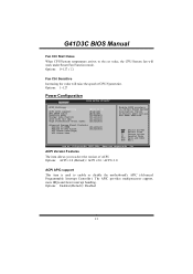
Bios Setup
Page 14
... Increasing the value will work under Smart Fan Function mode. ACPI Version Features The item allows you to select the version of CPU/System fan. G41D3C BIOS Manual Fan Ctrl Start Value When CPU/System temperature arrives to the set value, the CPU/System fan will raise the speed of ACPI... Controls Resume On PME# [Disabled] Resume On RTC Alarm [Disabled] RTC Alarm Date(Days) RTC Alarm Time Enable RSDP pointers to enable or disable the motherboard's APIC (Advanced Programmable Interrupt Controller). Different ACPI verison has some addition.
... Increasing the value will work under Smart Fan Function mode. ACPI Version Features The item allows you to select the version of CPU/System fan. G41D3C BIOS Manual Fan Ctrl Start Value When CPU/System temperature arrives to the set value, the CPU/System fan will raise the speed of ACPI... Controls Resume On PME# [Disabled] Resume On RTC Alarm [Disabled] RTC Alarm Date(Days) RTC Alarm Time Enable RSDP pointers to enable or disable the motherboard's APIC (Advanced Programmable Interrupt Controller). Different ACPI verison has some addition.
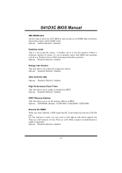
Bios Setup
Page 15
...lake feature. Options: FED00000h (Default) / FED01000h / FED02000h / FED03000h Resume On PME# When you may need a LAN add-on card which supports the Wake on motherboard to Full ON state. For this value to allow the ACPI BIOS to add a pointer to set the memory address of HPET. Windows Server 2003...allows you to an OEMB table in headless mode, both BIOS and operating system (e.g. Set the Wake on LAN (WOL) jumper on LAN function. G41D3C BIOS Manual AMI OEMB table Set this function to work, you select Enabled, a PME signal from PCI card returns the system to enable if applicable...
...lake feature. Options: FED00000h (Default) / FED01000h / FED02000h / FED03000h Resume On PME# When you may need a LAN add-on card which supports the Wake on motherboard to Full ON state. For this value to allow the ACPI BIOS to add a pointer to set the memory address of HPET. Windows Server 2003...allows you to an OEMB table in headless mode, both BIOS and operating system (e.g. Set the Wake on LAN (WOL) jumper on LAN function. G41D3C BIOS Manual AMI OEMB table Set this function to work, you select Enabled, a PME signal from PCI card returns the system to enable if applicable...


