
Setup Manual
Page 2
Table of Contents Chapter 1: Introduction 1 1.1 Before You Start 1 1.2 Package Checklist 1 1.3 Motherboard Features 2 1.4 Rear Panel Connectors 3 1.5 Motherboard Layout 4 Chapter 2: Hardware Installation 5 2.1 Installing Central Processing Unit (CPU 5 2.2 FAN Headers 7 2.3 Installing System Memory 8 2.4 Connectors and Slots 10 Chapter 3: Headers & Jumpers Setup 13 3.1 How to ...
Table of Contents Chapter 1: Introduction 1 1.1 Before You Start 1 1.2 Package Checklist 1 1.3 Motherboard Features 2 1.4 Rear Panel Connectors 3 1.5 Motherboard Layout 4 Chapter 2: Hardware Installation 5 2.1 Installing Central Processing Unit (CPU 5 2.2 FAN Headers 7 2.3 Installing System Memory 8 2.4 Connectors and Slots 10 Chapter 3: Headers & Jumpers Setup 13 3.1 How to ...

Setup Manual
Page 3
... the rear side of the computer should be different due to area or your motherboard version. 1 Before you start installing the motherboard, please make sure you follow the instructions below: „ Prepare a dry and stable working environment with sufficient lighting.... PACKAGE CHECKLIST HDD Cable X 1 (optional) Serial ATA Cable X 2 Rear I/O Panel for choosing our product. CHAPTER 1: INTRODUCTION G41 HD 1.1 BEFORE YOU START Thank you take the motherboard out from dangerous area, such as heat source, humid air and water. „ The operating temperatures of the board unless necessary.
... the rear side of the computer should be different due to area or your motherboard version. 1 Before you start installing the motherboard, please make sure you follow the instructions below: „ Prepare a dry and stable working environment with sufficient lighting.... PACKAGE CHECKLIST HDD Cable X 1 (optional) Serial ATA Cable X 2 Rear I/O Panel for choosing our product. CHAPTER 1: INTRODUCTION G41 HD 1.1 BEFORE YOU START Thank you take the motherboard out from dangerous area, such as heat source, humid air and water. „ The operating temperatures of the board unless necessary.

Setup Manual
Page 4
Motherboard Manual 1.3 MOTHERBOARD FEATURES SPEC LGA 775 Intel Core2Duo / Core2Quad / Supports Execute Disable Bit / Enhanced Intel CPU Pentium Dual-Core / Celeron Dual-Core / SpeedStep® / Intel Architecture-64 / Extended Celeron 4xx processor Memory 64 Technology / Virtualization Technology (Maximum Watt: 95W) FSB Support 800 / 1066 / 1333 MHz Chipset Intel G41 Intel ICH7 ITE 8721 Environment...
Motherboard Manual 1.3 MOTHERBOARD FEATURES SPEC LGA 775 Intel Core2Duo / Core2Quad / Supports Execute Disable Bit / Enhanced Intel CPU Pentium Dual-Core / Celeron Dual-Core / SpeedStep® / Intel Architecture-64 / Extended Celeron 4xx processor Memory 64 Technology / Virtualization Technology (Maximum Watt: 95W) FSB Support 800 / 1066 / 1333 MHz Chipset Intel G41 Intel ICH7 ITE 8721 Environment...
Setup Manual
Page 6
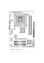
Motherboard Manual 1.5 MOTHERBOARD LAYOUT HDMI1 USBKB1 ATXPWR2 LGA775 CPU1 CPU_FAN1 ATX PW R 1 DVI1 D DR3_ A 1 D DR3_ B 1 VGA1 LAN JUSBV1 RJ45USB1 Intel G41 IDE1 AUDIO1 BAT1 Super I/O C odec F_AUDIO1 PEX16_1 JSPDIFOUT1 PCI1 Intel ICH7 BIOS JCMOS1 SATA4 CIR1 PCI2 J_PRINT1 J_COM1 JUSBV2 SATA3 SATA2 SYS_FAN1 F_USB1 F_USB2 PANEL1 SATA1 Note: ■ represents the 1st pin. 4
Motherboard Manual 1.5 MOTHERBOARD LAYOUT HDMI1 USBKB1 ATXPWR2 LGA775 CPU1 CPU_FAN1 ATX PW R 1 DVI1 D DR3_ A 1 D DR3_ B 1 VGA1 LAN JUSBV1 RJ45USB1 Intel G41 IDE1 AUDIO1 BAT1 Super I/O C odec F_AUDIO1 PEX16_1 JSPDIFOUT1 PCI1 Intel ICH7 BIOS JCMOS1 SATA4 CIR1 PCI2 J_PRINT1 J_COM1 JUSBV2 SATA3 SATA2 SYS_FAN1 F_USB1 F_USB2 PANEL1 SATA1 Note: ■ represents the 1st pin. 4
Setup Manual
Page 8
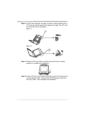
This completes the installation. 6 Connect the CPU FAN power cable into the CPU_FAN1. The CPU will fit only in the correct orientation. Step 4: Put the CPU Fan and heatsink assembly on the CPU and buckle it on CPU should point forwards this triangular cut edge on socket, and the golden dot on the retention frame. Step 2-1: Step 2-2: Step 3: Hold the CPU down firmly, and then lower the lever to locked position to complete the installation. Motherboard Manual Step 2: Look for the triangular cut edge.
This completes the installation. 6 Connect the CPU FAN power cable into the CPU_FAN1. The CPU will fit only in the correct orientation. Step 4: Put the CPU Fan and heatsink assembly on the CPU and buckle it on CPU should point forwards this triangular cut edge on socket, and the golden dot on the retention frame. Step 2-1: Step 2-2: Step 3: Hold the CPU down firmly, and then lower the lever to locked position to complete the installation. Motherboard Manual Step 2: Look for the triangular cut edge.
Setup Manual
Page 10
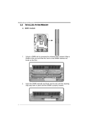
DDR3 module 1. Align a DIMM on the slot such that the notch on the DIMM matches the break on the Slot. 2. DDR3_A1 DDR3_B1 Motherboard Manual 2.3 INSTALLING SYSTEM MEMORY A. Insert the DIMM vertically and firmly into the slot until the retaining chip snap back in place and the DIMM is properly seated. 8 Unlock a DIMM slot by pressing the retaining clips outward.
DDR3 module 1. Align a DIMM on the slot such that the notch on the DIMM matches the break on the Slot. 2. DDR3_A1 DDR3_B1 Motherboard Manual 2.3 INSTALLING SYSTEM MEMORY A. Insert the DIMM vertically and firmly into the slot until the retaining chip snap back in place and the DIMM is properly seated. 8 Unlock a DIMM slot by pressing the retaining clips outward.

Setup Manual
Page 12
S ATA 4 S ATA 3 S ATA 2 S ATA 1 Pin Assignment 1 Ground 2 TX+ 3 TX4 Ground 5 RX6 RX+ 7 Ground 14 7 10 Motherboard Manual 2.4 CONNECTORS AND SLOTS IDE1: Hard Disk Connector The motherboard has a 32-bit Enhanced PCI IDE Controller that provides PIO Mode 0~4, Bus Master, and Ultra DMA 33/66/100 functionality. 40 39 2 1 SATA1~SATA4: Serial ATA Connectors The motherboard has a PCI to SATA Controller with 4channels SATA interface, it satisfies the SATA 2.0 spec and with transfer rate of 3Gb/s.
S ATA 4 S ATA 3 S ATA 2 S ATA 1 Pin Assignment 1 Ground 2 TX+ 3 TX4 Ground 5 RX6 RX+ 7 Ground 14 7 10 Motherboard Manual 2.4 CONNECTORS AND SLOTS IDE1: Hard Disk Connector The motherboard has a 32-bit Enhanced PCI IDE Controller that provides PIO Mode 0~4, Bus Master, and Ultra DMA 33/66/100 functionality. 40 39 2 1 SATA1~SATA4: Serial ATA Connectors The motherboard has a PCI to SATA Controller with 4channels SATA interface, it satisfies the SATA 2.0 spec and with transfer rate of 3Gb/s.

Setup Manual
Page 14
PEX16_1 PCI1/PCI2: Peripheral Component Interconnect Slots This motherboard is designated as 32 bits. PCI stands for Peripheral Component Interconnect, and it is a bus standard for an aggregate of 8GB/s totally. - PCI1 PCI2 12 Motherboard Manual PEX16_1: PCI-Express x16 Slot - PCI-Express 1.0a compliant. - This PCI slot is equipped with 2 standard PCI slots. PCI-Express supports a raw bit-rate of 4GB/s simultaneously per direction, for expansion cards. Maximum theoretical realized bandwidth of 2.5Gb/s on the data pins. - 2X bandwidth over the traditional PCI architecture.
PEX16_1 PCI1/PCI2: Peripheral Component Interconnect Slots This motherboard is designated as 32 bits. PCI stands for Peripheral Component Interconnect, and it is a bus standard for an aggregate of 8GB/s totally. - PCI1 PCI2 12 Motherboard Manual PEX16_1: PCI-Express x16 Slot - PCI-Express 1.0a compliant. - This PCI slot is equipped with 2 standard PCI slots. PCI-Express supports a raw bit-rate of 4GB/s simultaneously per direction, for expansion cards. Maximum theoretical realized bandwidth of 2.5Gb/s on the data pins. - 2X bandwidth over the traditional PCI architecture.
Setup Manual
Page 16
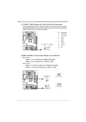
... 2.0 Ports at USBKB1/RJ45USB1. Pin 2-3 Close: JUSBV1: +5V STB for USB ports at F_USB1/F_USB2. JUSBV2: +5V STB for USB ports at Front Panel This motherboard provides 2 USB 2.0 headers, which allows user to connect additional USB cable on the PC front panel, and also can be connected with internal USB devices...
... 2.0 Ports at USBKB1/RJ45USB1. Pin 2-3 Close: JUSBV1: +5V STB for USB ports at F_USB1/F_USB2. JUSBV2: +5V STB for USB ports at Front Panel This motherboard provides 2 USB 2.0 headers, which allows user to connect additional USB cable on the PC front panel, and also can be connected with internal USB devices...
Setup Manual
Page 18
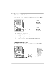
...Set the jumper to send 9 Ring indicator 10 Key 16 Please carefully follow the procedures to restore the BIOS safe setting and the CMOS data. Motherboard Manual JCMOS1: Clear CMOS Header Placing the jumper on the AC. 6. Reset your desired password or clear the CMOS data. Remove AC power line.... 2. Power on pin2-3 allows user to avoid damaging the motherboard. 13 Pin 1-2 Close: Normal Operation (Default). 13 13 Pin 2-3 Close: Clear CMOS data. ※ Clear CMOS Procedures: 1. J_COM1: Serial Port ...
...Set the jumper to send 9 Ring indicator 10 Key 16 Please carefully follow the procedures to restore the BIOS safe setting and the CMOS data. Motherboard Manual JCMOS1: Clear CMOS Header Placing the jumper on the AC. 6. Reset your desired password or clear the CMOS data. Remove AC power line.... 2. Power on pin2-3 allows user to avoid damaging the motherboard. 13 Pin 1-2 Close: Normal Operation (Default). 13 13 Pin 2-3 Close: Clear CMOS data. ※ Clear CMOS Procedures: 1. J_COM1: Serial Port ...

Setup Manual
Page 20
A. Software Installation To install the software, please click on the Driver icon. Motherboard Manual CHAPTER 4: USEFUL HELP 4.1 DRIVER INSTALLATION NOTE After you installed your operating system, please insert the Fully Setup Driver CD into your system, click on ...://www.adobe.com /produ cts/a crobat /reads tep2 .html 18 Click on the Manual icon to locate and execute the file SETUP.EXE under your motherboard and operating system. Note: You will list the software available for your optical drive and install the driver for your...
A. Software Installation To install the software, please click on the Driver icon. Motherboard Manual CHAPTER 4: USEFUL HELP 4.1 DRIVER INSTALLATION NOTE After you installed your operating system, please insert the Fully Setup Driver CD into your system, click on ...://www.adobe.com /produ cts/a crobat /reads tep2 .html 18 Click on the Manual icon to locate and execute the file SETUP.EXE under your motherboard and operating system. Note: You will list the software available for your optical drive and install the driver for your...
Setup Manual
Page 22
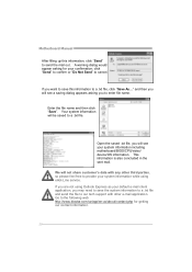
....txt file. Your system information will be saved to cancel. We will see your system information including motherboard/BIOS/CPU/video/ device/OS information. If you are not using Outlook Express as your default e-mail client...want to save the system information to a .txt file and send the file to provide your confirmation; Motherboard Manual After filling up this information to send the mail out. If you may need to save this ...txt file, you to the following web http://www.biostar.com.tw/app/en-us/about/contact.php for your system information while using eHot-Line service....
....txt file. Your system information will be saved to cancel. We will see your system information including motherboard/BIOS/CPU/video/ device/OS information. If you are not using Outlook Express as your default e-mail client...want to save the system information to a .txt file and send the file to provide your confirmation; Motherboard Manual After filling up this information to send the mail out. If you may need to save this ...txt file, you to the following web http://www.biostar.com.tw/app/en-us/about/contact.php for your system information while using eHot-Line service....
Setup Manual
Page 23
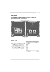
G41 HD BIOS Update BIOS Update is a convenient utility which allows you to a .bin file Update BIOS with a BIOS file Once click on this button, the saving dialog will show. AWARD BIOS Show current BIOS information AMI BIOS Clear CMOS function (Only for AWARD BIOS) Save current BIOS to update your motherboard BIOS under Windows system. Choose the position to save file and enter file name. (We recommend that the file name should be English/number and no longer than 7 characters.) Then click Save. 21
G41 HD BIOS Update BIOS Update is a convenient utility which allows you to a .bin file Update BIOS with a BIOS file Once click on this button, the saving dialog will show. AWARD BIOS Show current BIOS information AMI BIOS Clear CMOS function (Only for AWARD BIOS) Save current BIOS to update your motherboard BIOS under Windows system. Choose the position to save file and enter file name. (We recommend that the file name should be English/number and no longer than 7 characters.) Then click Save. 21

Setup Manual
Page 24
... process may be changed without notice. BIOS Update is being continuously updated. All the information and content above are subject to the Backup BIOS procedure; Motherboard Manual Before doing this procedure. Click Yes for updating, then click on board may take minutes. After the BIOS Backup procedure, the open any other...
... process may be changed without notice. BIOS Update is being continuously updated. All the information and content above are subject to the Backup BIOS procedure; Motherboard Manual Before doing this procedure. Click Yes for updating, then click on board may take minutes. After the BIOS Backup procedure, the open any other...

Setup Manual
Page 25
CPU fan speed is over heated, the motherboard will shutdown automatically to relief the CPU protection function. 1. Remove the power cord from power supply for seconds. 3. Power on system for seconds. 3. G41 HD 4.3 EXTRA INFORMATION CPU Overheated If the system shutdown automatically after power on the system again. 23 When the CPU is fulfilling...
CPU fan speed is over heated, the motherboard will shutdown automatically to relief the CPU protection function. 1. Remove the power cord from power supply for seconds. 3. Power on system for seconds. 3. G41 HD 4.3 EXTRA INFORMATION CPU Overheated If the system shutdown automatically after power on the system again. 23 When the CPU is fulfilling...

Setup Manual
Page 26
... (POST) procedure while booting up. z Shutting down or resetting the system while updating the BIOS will lead to download the latest BIOS file for the motherboard. 2. To enter the utility, press during the POST process. Then, save the BIOS file into a USB pen drive or a floppy disk...
... (POST) procedure while booting up. z Shutting down or resetting the system while updating the BIOS will lead to download the latest BIOS file for the motherboard. 2. To enter the utility, press during the POST process. Then, save the BIOS file into a USB pen drive or a floppy disk...

Setup Manual
Page 27
Before declaring the motherboard beyond all expansion cards except the video adapter. Fatal error indicating a serious problem with known good modules. Remove all hope, eliminate the possibility of interference ... Beep Codes Number of Beeps Troubleshooting Action 1, 3 Reseat the memory, or replace with the system. This will reveal the malfunctioning card. 4.4 AMI BIOS BEEP CODE G41 HD Boot Block Beep Codes Number of Beeps Description 1 No media present. (Insert diskette in floppy drive A:) 2 "AMIBOOT.ROM" file not found in root directory of...
Before declaring the motherboard beyond all expansion cards except the video adapter. Fatal error indicating a serious problem with known good modules. Remove all hope, eliminate the possibility of interference ... Beep Codes Number of Beeps Troubleshooting Action 1, 3 Reseat the memory, or replace with the system. This will reveal the malfunctioning card. 4.4 AMI BIOS BEEP CODE G41 HD Boot Block Beep Codes Number of Beeps Description 1 No media present. (Insert diskette in floppy drive A:) 2 "AMIBOOT.ROM" file not found in root directory of...

Setup Manual
Page 28
... lit, the DIMM, press down at any time. check the drive type in the system. 1. Call the drive manufacturers for compatibility with other drives. 26 Motherboard Manual 4.5 TROUBLESHOOTING Probable Solution 1. Make sure power cable is no power in the standard CMOS setup. 2. drive. second hard drive. 2. There is Power LED does...
... lit, the DIMM, press down at any time. check the drive type in the system. 1. Call the drive manufacturers for compatibility with other drives. 26 Motherboard Manual 4.5 TROUBLESHOOTING Probable Solution 1. Make sure power cable is no power in the standard CMOS setup. 2. drive. second hard drive. 2. There is Power LED does...

Bios Setup
Page 2
G41 HD BIOS Manual BIOS Setup Introduction T he purpose of the input and output devices such as keyboard, mouse, serial ports and disk drives. Basic Input-Output ... so that it retains theSetup information when the power is to guide you through the options and settings in the ACPI specification, developed by this motherboard. APM Support T his system controls most of this manual is turned off. BIOS activates at the first stag e o f the booting process, loading and executing the...
G41 HD BIOS Manual BIOS Setup Introduction T he purpose of the input and output devices such as keyboard, mouse, serial ports and disk drives. Basic Input-Output ... so that it retains theSetup information when the power is to guide you through the options and settings in the ACPI specification, developed by this motherboard. APM Support T his system controls most of this manual is turned off. BIOS activates at the first stag e o f the booting process, loading and executing the...

Bios Setup
Page 3
... performan ce of the selected item. G41 HD BIOS Manual PCI Bus Support T his AMI BIOS supports the Intel CPU. Use Load Setup Default under the Exit Menu. If the system becomes unstable after changing any mistakes found in this manual is providing a brief description of the motherboard. In the BIOS setup utility...
... performan ce of the selected item. G41 HD BIOS Manual PCI Bus Support T his AMI BIOS supports the Intel CPU. Use Load Setup Default under the Exit Menu. If the system becomes unstable after changing any mistakes found in this manual is providing a brief description of the motherboard. In the BIOS setup utility...

