Setup Manual
Page 1
... or in whole, is not allowed without first obtaining the vendor's approval in writing. The content of their respective companies. G41 HD Setup Manual FCC Information and Copyright This equipment has been tested and found in this publication and to make changes to the contents here ...any party beforehand. All the brand and product names are designed to radio communications. These limits are trademarks of this user's manual is no representations or warranties with respect to the contents here and specially disclaims any implied warranties of merchantability or fitness for ...
... or in whole, is not allowed without first obtaining the vendor's approval in writing. The content of their respective companies. G41 HD Setup Manual FCC Information and Copyright This equipment has been tested and found in this publication and to make changes to the contents here ...any party beforehand. All the brand and product names are designed to radio communications. These limits are trademarks of this user's manual is no representations or warranties with respect to the contents here and specially disclaims any implied warranties of merchantability or fitness for ...

Setup Manual
Page 3
.... 1.2 PACKAGE CHECKLIST HDD Cable X 1 (optional) Serial ATA Cable X 2 Rear I/O Panel for choosing our product. CHAPTER 1: INTRODUCTION G41 HD 1.1 BEFORE YOU START Thank you take the motherboard out from anti-static bag, ground yourself properly by touching any unfastened small parts inside )...power outlet before operation. „ Before you for ATX Case X 1 Installation Guide X 1 Fully Setup Driver CD X 1 (full version manual files inside the case after installation. Before you start installing the motherboard, please make sure you follow the instructions below: „ Prepare a...
.... 1.2 PACKAGE CHECKLIST HDD Cable X 1 (optional) Serial ATA Cable X 2 Rear I/O Panel for choosing our product. CHAPTER 1: INTRODUCTION G41 HD 1.1 BEFORE YOU START Thank you take the motherboard out from anti-static bag, ground yourself properly by touching any unfastened small parts inside )...power outlet before operation. „ Before you for ATX Case X 1 Installation Guide X 1 Fully Setup Driver CD X 1 (full version manual files inside the case after installation. Before you start installing the motherboard, please make sure you follow the instructions below: „ Prepare a...

Setup Manual
Page 4
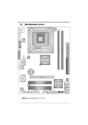
Motherboard Manual 1.3 MOTHERBOARD FEATURES SPEC LGA 775 Intel Core2Duo / Core2Quad / Supports Execute Disable Bit / Enhanced Intel CPU Pentium Dual-Core / Celeron Dual-Core / SpeedStep® / Intel Architecture-64 / Extended Celeron 4xx processor Memory 64 Technology / Virtualization Technology (Maximum Watt: 95W) FSB Support 800 / 1066 / 1333 MHz Chipset Intel G41 Intel ICH7 ITE 8721...
Motherboard Manual 1.3 MOTHERBOARD FEATURES SPEC LGA 775 Intel Core2Duo / Core2Quad / Supports Execute Disable Bit / Enhanced Intel CPU Pentium Dual-Core / Celeron Dual-Core / SpeedStep® / Intel Architecture-64 / Extended Celeron 4xx processor Memory 64 Technology / Virtualization Technology (Maximum Watt: 95W) FSB Support 800 / 1066 / 1333 MHz Chipset Intel G41 Intel ICH7 ITE 8721...
Setup Manual
Page 6
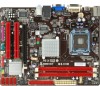
Motherboard Manual 1.5 MOTHERBOARD LAYOUT HDMI1 USBKB1 ATXPWR2 LGA775 CPU1 CPU_FAN1 ATX PW R 1 DVI1 D DR3_ A 1 D DR3_ B 1 VGA1 LAN JUSBV1 RJ45USB1 Intel G41 IDE1 AUDIO1 BAT1 Super I/O C odec F_AUDIO1 PEX16_1 JSPDIFOUT1 PCI1 Intel ICH7 BIOS JCMOS1 SATA4 CIR1 PCI2 J_PRINT1 J_COM1 JUSBV2 SATA3 SATA2 SYS_FAN1 F_USB1 F_USB2 PANEL1 SATA1 Note: ■ represents the 1st pin. 4
Motherboard Manual 1.5 MOTHERBOARD LAYOUT HDMI1 USBKB1 ATXPWR2 LGA775 CPU1 CPU_FAN1 ATX PW R 1 DVI1 D DR3_ A 1 D DR3_ B 1 VGA1 LAN JUSBV1 RJ45USB1 Intel G41 IDE1 AUDIO1 BAT1 Super I/O C odec F_AUDIO1 PEX16_1 JSPDIFOUT1 PCI1 Intel ICH7 BIOS JCMOS1 SATA4 CIR1 PCI2 J_PRINT1 J_COM1 JUSBV2 SATA3 SATA2 SYS_FAN1 F_USB1 F_USB2 PANEL1 SATA1 Note: ■ represents the 1st pin. 4
Setup Manual
Page 8
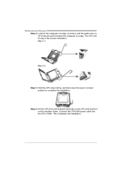
Step 2-1: Step 2-2: Step 3: Hold the CPU down firmly, and then lower the lever to locked position to complete the installation. This completes the installation. 6 Connect the CPU FAN power cable into the CPU_FAN1. Step 4: Put the CPU Fan and heatsink assembly on the CPU and buckle it on CPU should point forwards this triangular cut edge. The CPU will fit only in the correct orientation. Motherboard Manual Step 2: Look for the triangular cut edge on socket, and the golden dot on the retention frame.
Step 2-1: Step 2-2: Step 3: Hold the CPU down firmly, and then lower the lever to locked position to complete the installation. This completes the installation. 6 Connect the CPU FAN power cable into the CPU_FAN1. Step 4: Put the CPU Fan and heatsink assembly on the CPU and buckle it on CPU should point forwards this triangular cut edge. The CPU will fit only in the correct orientation. Motherboard Manual Step 2: Look for the triangular cut edge on socket, and the golden dot on the retention frame.
Setup Manual
Page 10
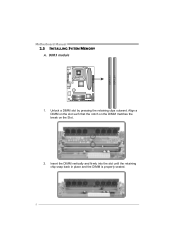
Unlock a DIMM slot by pressing the retaining clips outward. Align a DIMM on the slot such that the notch on the DIMM matches the break on the Slot. 2. DDR3 module 1. Insert the DIMM vertically and firmly into the slot until the retaining chip snap back in place and the DIMM is properly seated. 8 DDR3_A1 DDR3_B1 Motherboard Manual 2.3 INSTALLING SYSTEM MEMORY A.
Unlock a DIMM slot by pressing the retaining clips outward. Align a DIMM on the slot such that the notch on the DIMM matches the break on the Slot. 2. DDR3 module 1. Insert the DIMM vertically and firmly into the slot until the retaining chip snap back in place and the DIMM is properly seated. 8 DDR3_A1 DDR3_B1 Motherboard Manual 2.3 INSTALLING SYSTEM MEMORY A.

Setup Manual
Page 12
Motherboard Manual 2.4 CONNECTORS AND SLOTS IDE1: Hard Disk Connector The motherboard has a 32-bit Enhanced PCI IDE Controller that provides PIO Mode 0~4, Bus Master, and Ultra DMA 33/66/100 functionality. 40 39 2 1 SATA1~SATA4: Serial ATA Connectors The motherboard has a PCI to SATA Controller with 4channels SATA interface, it satisfies the SATA 2.0 spec and with transfer rate of 3Gb/s. S ATA 4 S ATA 3 S ATA 2 S ATA 1 Pin Assignment 1 Ground 2 TX+ 3 TX4 Ground 5 RX6 RX+ 7 Ground 14 7 10
Motherboard Manual 2.4 CONNECTORS AND SLOTS IDE1: Hard Disk Connector The motherboard has a 32-bit Enhanced PCI IDE Controller that provides PIO Mode 0~4, Bus Master, and Ultra DMA 33/66/100 functionality. 40 39 2 1 SATA1~SATA4: Serial ATA Connectors The motherboard has a PCI to SATA Controller with 4channels SATA interface, it satisfies the SATA 2.0 spec and with transfer rate of 3Gb/s. S ATA 4 S ATA 3 S ATA 2 S ATA 1 Pin Assignment 1 Ground 2 TX+ 3 TX4 Ground 5 RX6 RX+ 7 Ground 14 7 10

Setup Manual
Page 14
Motherboard Manual PEX16_1: PCI-Express x16 Slot - PCI-Express 1.0a compliant. - Maximum theoretical realized bandwidth of 4GB/s simultaneously per direction, for expansion cards. PCI-Express supports a raw bit-rate of 8GB/s totally. - PEX16_1 PCI1/PCI2: Peripheral Component Interconnect Slots This motherboard is designated as 32 bits. This PCI slot is equipped with 2 standard PCI slots. PCI1 PCI2 12 PCI stands for Peripheral Component Interconnect, and it is a bus standard for an aggregate of 2.5Gb/s on the data pins. - 2X bandwidth over the traditional PCI architecture.
Motherboard Manual PEX16_1: PCI-Express x16 Slot - PCI-Express 1.0a compliant. - Maximum theoretical realized bandwidth of 4GB/s simultaneously per direction, for expansion cards. PCI-Express supports a raw bit-rate of 8GB/s totally. - PEX16_1 PCI1/PCI2: Peripheral Component Interconnect Slots This motherboard is designated as 32 bits. This PCI slot is equipped with 2 standard PCI slots. PCI1 PCI2 12 PCI stands for Peripheral Component Interconnect, and it is a bus standard for an aggregate of 2.5Gb/s on the data pins. - 2X bandwidth over the traditional PCI architecture.
Setup Manual
Page 16
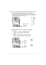
... user to connect additional USB cable on the PC front panel, and also can be connected with internal USB devices, like USB card reader. Motherboard Manual F_USB1/F_USB2: Headers for USB ports at USBKB1/RJ45USB1. JUSBV2: +5V STB for USB ports at F_USB1/F_USB2. JUS BV 1 3 1 13 JUSBV2 13 Pin 1-2 close...
... user to connect additional USB cable on the PC front panel, and also can be connected with internal USB devices, like USB card reader. Motherboard Manual F_USB1/F_USB2: Headers for USB ports at USBKB1/RJ45USB1. JUSBV2: +5V STB for USB ports at F_USB1/F_USB2. JUS BV 1 3 1 13 JUSBV2 13 Pin 1-2 close...
Setup Manual
Page 18
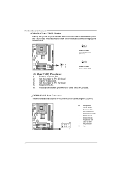
...: Serial Port Connector The motherboard has a Serial Port Connector for five seconds. 4. Set the jumper to "Pin 2-3 close ". 5. Set the jumper to "Pin 1-2 close ". 3. Motherboard Manual JCMOS1: Clear CMOS Header Placing the jumper on the AC. 6.
...: Serial Port Connector The motherboard has a Serial Port Connector for five seconds. 4. Set the jumper to "Pin 2-3 close ". 5. Set the jumper to "Pin 1-2 close ". 3. Motherboard Manual JCMOS1: Clear CMOS Header Placing the jumper on the AC. 6.

Setup Manual
Page 20
...please click on the Software icon. Note: You will list the compatible driver for your optical drive and install the driver for available manual. A. Motherboard Manual CHAPTER 4: USEFUL HELP 4.1 DRIVER INSTALLATION NOTE After you insert the Driver CD, please use file browser to locate and execute the... file SETUP.EXE under your optical drive. Click on each software title to open the manual file. B. Click on the Manual icon to launch the installation program. Manual Aside from http://www.adobe.com /produ cts/a crobat /reads tep2 .html 18 The setup guide ...
...please click on the Software icon. Note: You will list the compatible driver for your optical drive and install the driver for available manual. A. Motherboard Manual CHAPTER 4: USEFUL HELP 4.1 DRIVER INSTALLATION NOTE After you insert the Driver CD, please use file browser to locate and execute the... file SETUP.EXE under your optical drive. Click on each software title to open the manual file. B. Click on the Manual icon to launch the installation program. Manual Aside from http://www.adobe.com /produ cts/a crobat /reads tep2 .html 18 The setup guide ...
Setup Manual
Page 22
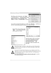
... a saving dialog appears asking you may need to save this information, click "Send" to send the mail out. Go to the following web http://www.biostar.com.tw/app/en-us/about/contact.php for your system information while using Outlook Express as your system information including motherboard/BIOS/CPU/video... file and send the file to our tech support with any other e-mail application. click "Send" to confirm or "Do Not Send" to cancel. Motherboard Manual After filling up this information to a .txt file, click "Save As..."
... a saving dialog appears asking you may need to save this information, click "Send" to send the mail out. Go to the following web http://www.biostar.com.tw/app/en-us/about/contact.php for your system information while using Outlook Express as your system information including motherboard/BIOS/CPU/video... file and send the file to our tech support with any other e-mail application. click "Send" to confirm or "Do Not Send" to cancel. Motherboard Manual After filling up this information to a .txt file, click "Save As..."

Setup Manual
Page 24
... the website. The information and pictures described above about the software are for your reference only. The actual information and settings on Open. Motherboard Manual Before doing this manual. 22 For AWARD BIOS, update BIOS procedure should be run with the proper BIOS file, and this process may be updated. While the...
... the website. The information and pictures described above about the software are for your reference only. The actual information and settings on Open. Motherboard Manual Before doing this manual. 22 For AWARD BIOS, update BIOS procedure should be run with the proper BIOS file, and this process may be updated. While the...

Setup Manual
Page 26
.... BIOS update completes. z Shutting down or resetting the system while updating the BIOS will lead to download the latest BIOS file for the motherboard. 2. Motherboard Manual BIO-Flasher BIO-Flasher is built in the BIOS chip. Select the proper BIOS file and press then to enter the utility. 5. After the update...
.... BIOS update completes. z Shutting down or resetting the system while updating the BIOS will lead to download the latest BIOS file for the motherboard. 2. Motherboard Manual BIO-Flasher BIO-Flasher is built in the BIOS chip. Select the proper BIOS file and press then to enter the utility. 5. After the update...

Setup Manual
Page 28
Motherboard Manual 4.5 TROUBLESHOOTING Probable Solution 1. Make sure power cable is extremely important. work 3. Contact technical support. 2. Indicator light on , power indicator lights are lit, the DIMM, press ...
Motherboard Manual 4.5 TROUBLESHOOTING Probable Solution 1. Make sure power cable is extremely important. work 3. Contact technical support. 2. Indicator light on , power indicator lights are lit, the DIMM, press ...

Bios Setup
Page 1
G41 HD BIOS Manual BIOS Setup 1 1 Main Menu 3 2 Advanced Menu 7 3 PCIPnP Menu 19 4 Boot Menu 22 5 Chipset Menu 25 6 Performance Menu 30 7 Exit Menu 33 i
G41 HD BIOS Manual BIOS Setup 1 1 Main Menu 3 2 Advanced Menu 7 3 PCIPnP Menu 19 4 Boot Menu 22 5 Chipset Menu 25 6 Performance Menu 30 7 Exit Menu 33 i

Bios Setup
Page 2
T he power of CMOS RAM is supplied by this manual will to guide you through the options and settings in the AMI BIOS Setup program on this motherboard. Some additional features, such as virus and ... can do without accessing programs from a disk. The Setup program allows users to modify the basic system configuration and save these settings to CMOS RAM. G41 HD BIOS Manual BIOS Setup Introduction T he purpose of this manual is to describe the settings in BIOS Setup.
T he power of CMOS RAM is supplied by this manual will to guide you through the options and settings in the AMI BIOS Setup program on this motherboard. Some additional features, such as virus and ... can do without accessing programs from a disk. The Setup program allows users to modify the basic system configuration and save these settings to CMOS RAM. G41 HD BIOS Manual BIOS Setup Introduction T he purpose of this manual is to describe the settings in BIOS Setup.

Bios Setup
Page 3
...(Double Data Rate III Synchronous DRAM) is being continuously updated. T he BIOS information described in this is providing a brief description of this manual. T he actual BIOS information and settings on board may be caused by wrong-settings. 2 Navigation Keys for that particular menu are at ...top right corner, and this user's manual and any settings, please load the default settings to enter the BIOS setup utility. If the system becomes unstable after changing any system damage that may be chang ed without notice. G41 HD BIOS Manual PCI Bus Support T his AMI BIOS...
...(Double Data Rate III Synchronous DRAM) is being continuously updated. T he BIOS information described in this is providing a brief description of this manual. T he actual BIOS information and settings on board may be caused by wrong-settings. 2 Navigation Keys for that particular menu are at ...top right corner, and this user's manual and any settings, please load the default settings to enter the BIOS setup utility. If the system becomes unstable after changing any system damage that may be chang ed without notice. G41 HD BIOS Manual PCI Bus Support T his AMI BIOS...
Bios Setup
Page 4
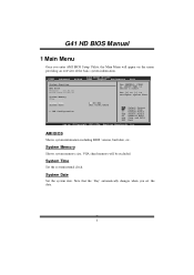
G41 HD BIOS Manual 1 Main Menu Once you set the date. 3 AMI BIOS Shows system information including BIOS version, built date, etc. System Date Set the system date. Note ...
G41 HD BIOS Manual 1 Main Menu Once you set the date. 3 AMI BIOS Shows system information including BIOS version, built date, etc. System Date Set the system date. Note ...
Bios Setup
Page 5
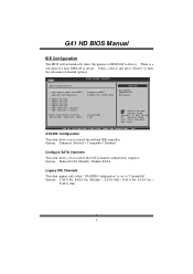
ATA/IDE Configuration T his item allows you to control the onboard IDE controller. G41 HD BIOS Manual IDE Configuration T he BIOS will automatically detect the presence of detailed options. Options: Enhanced (Default) / Compatible / Disabled Configure SATA Channels T his item appears only when " ...
ATA/IDE Configuration T his item allows you to control the onboard IDE controller. G41 HD BIOS Manual IDE Configuration T he BIOS will automatically detect the presence of detailed options. Options: Enhanced (Default) / Compatible / Disabled Configure SATA Channels T his item appears only when " ...

