
Setup Manual
Page 2
... System 17 4.2 Raid Arrays 17 4.3 How RAID Works 17 Chapter 5: Useful Help 20 5.1 Driver Installation Note 20 5.2 Software 21 5.3 Extra Information 25 5.4 Troubleshooting 27 Appendix: SPEC In Other Languages 28 German ...28 French ...30 Italian ...32 Spanish ...34 Portuguese...36 Polish ...38 Russian ...40 Arabic ...42 Japanese...44
... System 17 4.2 Raid Arrays 17 4.3 How RAID Works 17 Chapter 5: Useful Help 20 5.1 Driver Installation Note 20 5.2 Software 21 5.3 Extra Information 25 5.4 Troubleshooting 27 Appendix: SPEC In Other Languages 28 German ...28 French ...30 Italian ...32 Spanish ...34 Portuguese...36 Polish ...38 Russian ...40 Arabic ...42 Japanese...44

Setup Manual
Page 4
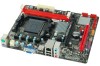
Motherboard Manual 1.3 MOTHERBOARD FEATURES SPEC Socket AM3 / AM3+ AMD 64 Architecture enables 32 and 64 bit computing CPU AMD Sempron/Athlon II / Phenom II /FX Supports Hyper Transport 3.0 processors (Maximum ... Max Shared Video Memory is 512MB SATA II Integrated Serial ATA Controller Data transfer rates up to 3 Gb/s SATA Version 2.0 specification compliant Realtek RTL 8111F (A960G+) LAN Realtek RTL 8105E (A960GL+) 10 / 100 / 1000 Mb/s auto negotiation 10 / 100 Mb/s auto negotiation Sound ALC662 5.1 channels audio out High Definition Audio Slots...
Motherboard Manual 1.3 MOTHERBOARD FEATURES SPEC Socket AM3 / AM3+ AMD 64 Architecture enables 32 and 64 bit computing CPU AMD Sempron/Athlon II / Phenom II /FX Supports Hyper Transport 3.0 processors (Maximum ... Max Shared Video Memory is 512MB SATA II Integrated Serial ATA Controller Data transfer rates up to 3 Gb/s SATA Version 2.0 specification compliant Realtek RTL 8111F (A960G+) LAN Realtek RTL 8105E (A960GL+) 10 / 100 / 1000 Mb/s auto negotiation 10 / 100 Mb/s auto negotiation Sound ALC662 5.1 channels audio out High Definition Audio Slots...

Setup Manual
Page 5
... I/O LAN port USB Port Audio Jack Board Size 182 mm(W) x 225 mm(L) Special Features RAID 0 / 1 / 10 support OS Support Windows XP / Vista / 7 SPEC A960G+/A960GL+ x1 System Fan Power supply x1 Restore CMOS data to factory default setting x2 Each connector supports 2 front panel USB ports x1 Connects to...x1 Connect to D-SUB monitor x1 Connect to RJ-45 Ethernet cable x4 Connect to USB devices x3 Provide Audio-In/Out and microphone connection Biostar reserves the right to add or remove support for any OS With or without notice. 1.4 REAR PANEL CONNECTORS PS/2 Mouse PS/2 Keyboard ...
... I/O LAN port USB Port Audio Jack Board Size 182 mm(W) x 225 mm(L) Special Features RAID 0 / 1 / 10 support OS Support Windows XP / Vista / 7 SPEC A960G+/A960GL+ x1 System Fan Power supply x1 Restore CMOS data to factory default setting x2 Each connector supports 2 front panel USB ports x1 Connects to...x1 Connect to D-SUB monitor x1 Connect to RJ-45 Ethernet cable x4 Connect to USB devices x3 Provide Audio-In/Out and microphone connection Biostar reserves the right to add or remove support for any OS With or without notice. 1.4 REAR PANEL CONNECTORS PS/2 Mouse PS/2 Keyboard ...

Setup Manual
Page 8
... product warranty does not cover damage caused by overclocking (even when overclocking is designed for AMD 95W AM3/AM3+ CPU, pleases check the CPU TDP spec before you use AMD original box CPU fan and add an extra system fan inside the chassis. 6 Motherboard Manual Step 3: Hold the CPU down firmly... AM3+ CPU designation, we strongly recommend you install it on the CPU and buckle it. Step 4: Put the CPU Fan on MB AM3+ CPU TDP spec from below weblink: http://www.amd.com/us /products/desktop/processors/amdfx/Pages/amdfx.aspx 3. Note: 1. This completes the installation. This MB is enabled ...
... product warranty does not cover damage caused by overclocking (even when overclocking is designed for AMD 95W AM3/AM3+ CPU, pleases check the CPU TDP spec before you use AMD original box CPU fan and add an extra system fan inside the chassis. 6 Motherboard Manual Step 3: Hold the CPU down firmly... AM3+ CPU designation, we strongly recommend you install it on the CPU and buckle it. Step 4: Put the CPU Fan on MB AM3+ CPU TDP spec from below weblink: http://www.amd.com/us /products/desktop/processors/amdfx/Pages/amdfx.aspx 3. Note: 1. This completes the installation. This MB is enabled ...

Setup Manual
Page 12
Pin Assignment 1 +12V 2 +12V 3 Ground 4 Ground 10 Pin Assignment 1 Ground 2 TX+ 3 TX4 Ground 5 RX6 RX+ 7 Ground ATXPWR2: ATX Power Source Connector This connector provides +12V to SATA Controller with 4channels SATA interface, it satisfies the SATA 2.0 spec and with transfer rate of 3Gb/s. Motherboard Manual 2.4 CONNECTORS AND SLOTS SATA1~SATA4: Serial ATA Connectors The motherboard has a PCI to CPU power circuit.
Pin Assignment 1 +12V 2 +12V 3 Ground 4 Ground 10 Pin Assignment 1 Ground 2 TX+ 3 TX4 Ground 5 RX6 RX+ 7 Ground ATXPWR2: ATX Power Source Connector This connector provides +12V to SATA Controller with 4channels SATA interface, it satisfies the SATA 2.0 spec and with transfer rate of 3Gb/s. Motherboard Manual 2.4 CONNECTORS AND SLOTS SATA1~SATA4: Serial ATA Connectors The motherboard has a PCI to CPU power circuit.