
Setup Manual
Page 2
... You Start 1 1.2 Package Checklist 1 1.3 Motherboard Features 2 1.4 Rear Panel Connectors 3 1.5 Motherboard Layout 4 Chapter 2: Hardware Installation 5 2.1 Installing Central Processing Unit (CPU 5 2.2 FAN Headers 7 2.3 Installing System Memory 8 2.4 Connectors and Slots 10 Chapter 3: Headers & Jumpers Setup 13 3.1 How to Setup Jumpers 13 3.2 Detail Settings 13 Chapter 4: Hybrid CrossFireX Function (for A780G M2+ SE/ A780V M2+ SE 20 4.1 Hybrid CrossFireX Requirements 20...
... You Start 1 1.2 Package Checklist 1 1.3 Motherboard Features 2 1.4 Rear Panel Connectors 3 1.5 Motherboard Layout 4 Chapter 2: Hardware Installation 5 2.1 Installing Central Processing Unit (CPU 5 2.2 FAN Headers 7 2.3 Installing System Memory 8 2.4 Connectors and Slots 10 Chapter 3: Headers & Jumpers Setup 13 3.1 How to Setup Jumpers 13 3.2 Detail Settings 13 Chapter 4: Hybrid CrossFireX Function (for A780G M2+ SE/ A780V M2+ SE 20 4.1 Hybrid CrossFireX Requirements 20...

Setup Manual
Page 3
... use grounded wrist strap to remove the static charge. „ Avoid touching the components on motherboard or the rear side of the board unless necessary. A780G M2+ SE/A780V M2+ SE/A740G M2+ SE CHAPTER 1: INTRODUCTION 1.1 BEFORE YOU START Thank you take the motherboard out from dangerous area, such as heat source, humid air and water. 1.2 PACKAGE CHECKLIST HDD...
... use grounded wrist strap to remove the static charge. „ Avoid touching the components on motherboard or the rear side of the board unless necessary. A780G M2+ SE/A780V M2+ SE/A740G M2+ SE CHAPTER 1: INTRODUCTION 1.1 BEFORE YOU START Thank you take the motherboard out from dangerous area, such as heat source, humid air and water. 1.2 PACKAGE CHECKLIST HDD...

Setup Manual
Page 4
... FSB Chipset Super I/O Main Memory Graphics IDE SATA II LAN MOTHERBOARD FEATURES A780G M2+ SE/A780V M2+ SE A740G M2+ SE Socket AM2+ / AM2 Socket AM2+ / AM2 AMD Athlon 64 / Athlon 64 FX / Athlon 64 x2 / AMD Athlon 64 / Athlon 64 FX / Athlon 64 ... Hyper Transport 2.0 and PowerNow Support HyperTransport 3.0 Support HyperTransport 2.0 Supports up to 5.2 GT/s Bandwidth Supports up to 2.0 GT/s Bandwidth AMD 780G (A780G M2+ SE) AMD 780V (A780V M2+ SE) AMD SB700 AMD 740G AMD SB700 ITE 8718F ITE 8718F Provides the most commonly used legacy Super Provides the most commonly used legacy Super...
... FSB Chipset Super I/O Main Memory Graphics IDE SATA II LAN MOTHERBOARD FEATURES A780G M2+ SE/A780V M2+ SE A740G M2+ SE Socket AM2+ / AM2 Socket AM2+ / AM2 AMD Athlon 64 / Athlon 64 FX / Athlon 64 x2 / AMD Athlon 64 / Athlon 64 FX / Athlon 64 ... Hyper Transport 2.0 and PowerNow Support HyperTransport 3.0 Support HyperTransport 2.0 Supports up to 5.2 GT/s Bandwidth Supports up to 2.0 GT/s Bandwidth AMD 780G (A780G M2+ SE) AMD 780V (A780V M2+ SE) AMD SB700 AMD 740G AMD SB700 ITE 8718F ITE 8718F Provides the most commonly used legacy Super Provides the most commonly used legacy Super...

Setup Manual
Page 6
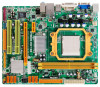
SATA6 SATA5 SATA4 BIOS AMD SB700 SATA3 JCMOS1 SATA2 JUSBV2 JSFAN1 SATA1 JUSB4 JUSB3 JUSB2 JPANEL1 4 Motherboard Manual 1.5 MOTHERBOARD LAYOUT JKBMS1 JATXPWR2 JKBV1 JCFAN1 JATXPWR1 Socket AM2+ DVI VGA DI MMA1 DI MMB1 JUSB1 JUSBLAN1 JUSBV1 BAT1 IDE1 JAUDIO1 JAUDIOF1 JCDIN1 JSPDIF_OUT1 LAN PEX1_1 AMD 780G/ 780V/ 740G Super I/O PEX16_1 PCI1 Codec JPRNT1 JCOM1 PCI2 FDD1 Note: ■ represents the 1st pin.
SATA6 SATA5 SATA4 BIOS AMD SB700 SATA3 JCMOS1 SATA2 JUSBV2 JSFAN1 SATA1 JUSB4 JUSB3 JUSB2 JPANEL1 4 Motherboard Manual 1.5 MOTHERBOARD LAYOUT JKBMS1 JATXPWR2 JKBV1 JCFAN1 JATXPWR1 Socket AM2+ DVI VGA DI MMA1 DI MMB1 JUSB1 JUSBLAN1 JUSBV1 BAT1 IDE1 JAUDIO1 JAUDIOF1 JCDIN1 JSPDIF_OUT1 LAN PEX1_1 AMD 780G/ 780V/ 740G Super I/O PEX16_1 PCI1 Codec JPRNT1 JCOM1 PCI2 FDD1 Note: ■ represents the 1st pin.

Setup Manual
Page 8
.... Due to the latest CPU transition, you may encounter the situation that the new system failed to the latest version while using new AM2+ CPUs. Motherboard Manual Step 4: Hold the CPU down firmly, and then close the lever toward direct B to complete the installation.
.... Due to the latest CPU transition, you may encounter the situation that the new system failed to the latest version while using new AM2+ CPUs. Motherboard Manual Step 4: Hold the CPU down firmly, and then close the lever toward direct B to complete the installation.

Setup Manual
Page 10
Memory Modules 1. Insert the DIMM vertically and firmly into the slot until the retaining chip snap back in place and the DIMM is properly seated. 8 DIMMA1 DIMMB1 Motherboard Manual 2.3 INSTALLING SYSTEM MEMORY A. Align a DIMM on the slot such that the notch on the DIMM matches the break on the Slot. 2. Unlock a DIMM slot by pressing the retaining clips outward.
Memory Modules 1. Insert the DIMM vertically and firmly into the slot until the retaining chip snap back in place and the DIMM is properly seated. 8 DIMMA1 DIMMB1 Motherboard Manual 2.3 INSTALLING SYSTEM MEMORY A. Align a DIMM on the slot such that the notch on the DIMM matches the break on the Slot. 2. Unlock a DIMM slot by pressing the retaining clips outward.

Setup Manual
Page 11
... density in pairs, shown in the following requirements: Install memory module of the motherboard, the memory module must be the same (x8 or x16) 9 Memory Capacity DIMM Socket Location DIMMA1 DIMMB1 DDR2 Module Total Memory Size 256MB/512MB/1GB/2GB/4GB Max is 8GB. 256MB/512MB/1GB/2GB/4GB C. A780G M2+ SE/A780V M2+ SE/A740G M2+ SE B.
... density in pairs, shown in the following requirements: Install memory module of the motherboard, the memory module must be the same (x8 or x16) 9 Memory Capacity DIMM Socket Location DIMMA1 DIMMB1 DDR2 Module Total Memory Size 256MB/512MB/1GB/2GB/4GB Max is 8GB. 256MB/512MB/1GB/2GB/4GB C. A780G M2+ SE/A780V M2+ SE/A740G M2+ SE B.

Setup Manual
Page 12
Motherboard Manual 2.4 CONNECTORS AND SLOTS FDD1: Floppy Disk Connector The motherboard provides a standard floppy disk connector that provides PIO Mode 0~4, Bus Master, and Ultra DMA 33/66/100/133 functionality. This connector supports the provided floppy drive ribbon cable. 2 34 1 33 IDE1: IDE/ATAPI Connector The motherboard has a 32-bit Enhanced PCI IDE Controller that supports 360K, 720K, 1.2M, 1.44M and 2.88M floppy disk types. The IDE connector can connect a master and a slave drive, so you can connect up to two drives. 40 39 21 10
Motherboard Manual 2.4 CONNECTORS AND SLOTS FDD1: Floppy Disk Connector The motherboard provides a standard floppy disk connector that provides PIO Mode 0~4, Bus Master, and Ultra DMA 33/66/100/133 functionality. This connector supports the provided floppy drive ribbon cable. 2 34 1 33 IDE1: IDE/ATAPI Connector The motherboard has a 32-bit Enhanced PCI IDE Controller that supports 360K, 720K, 1.2M, 1.44M and 2.88M floppy disk types. The IDE connector can connect a master and a slave drive, so you can connect up to two drives. 40 39 21 10

Setup Manual
Page 14
Motherboard Manual PCI1~PCI2: Peripheral Component Interconnect Slots This motherboard is a bus standard for expansion cards. PCI1 PCI2 12 PCI stands for Peripheral Component Interconnect, and it is equipped with 2 standard PCI slots. This PCI slot is designated as 32 bits.
Motherboard Manual PCI1~PCI2: Peripheral Component Interconnect Slots This motherboard is a bus standard for expansion cards. PCI1 PCI2 12 PCI stands for Peripheral Component Interconnect, and it is equipped with 2 standard PCI slots. This PCI slot is designated as 32 bits.

Setup Manual
Page 16
Motherboard Manual JATXPWR1: ATX Power Source Connector This connector allows user to connect 24-pin power connector on the ATX power supply. 12 24 Pin Assignment ...
Motherboard Manual JATXPWR1: ATX Power Source Connector This connector allows user to connect 24-pin power connector on the ATX power supply. 12 24 Pin Assignment ...
Setup Manual
Page 17
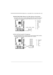
...~SATA6: Serial ATA Connectors The motherboard has a PCI to connect additional USB cable on the PC front panel, and also can be connected with transfer rate of 3.0Gb/s. SATA6 SATA5 SATA4 SATA3 SATA2 SATA1 741 Pin Assignment 1 Ground 2 TX+ 3 TX4 Ground 5 RX6 RX+ 7 Ground 15 A780G M2+ SE/A780V M2+ SE/A740G M2+ SE JUSB2/JUSB3/JUSB4: Headers...
...~SATA6: Serial ATA Connectors The motherboard has a PCI to connect additional USB cable on the PC front panel, and also can be connected with transfer rate of 3.0Gb/s. SATA6 SATA5 SATA4 SATA3 SATA2 SATA1 741 Pin Assignment 1 Ground 2 TX+ 3 TX4 Ground 5 RX6 RX+ 7 Ground 15 A780G M2+ SE/A780V M2+ SE/A740G M2+ SE JUSB2/JUSB3/JUSB4: Headers...

Setup Manual
Page 18
Pin Assignment 1 +5V 2 SPDIF_OUT 1 3 Ground 3 JAUDIOF1: Front Panel Audio Header This header allows user to connect the PCI bracket SPDIF output header. AC'97 connector is not acceptable. 10 9 2 1 Pin Assignment 1 Mic Left in 2 Ground 3 Mic Right in 4 GPIO 5 Right line in 6 Jack Sense 7 Front Sense 8 Key 9 Left line in 10 Jack Sense 16 This header allows only HD audio front panel connector; Motherboard Manual JSPDIF_OUT1: Digital Audio-out Connector This connector allows user to connect the front audio output cable with the PC front panel.
Pin Assignment 1 +5V 2 SPDIF_OUT 1 3 Ground 3 JAUDIOF1: Front Panel Audio Header This header allows user to connect the PCI bracket SPDIF output header. AC'97 connector is not acceptable. 10 9 2 1 Pin Assignment 1 Mic Left in 2 Ground 3 Mic Right in 4 GPIO 5 Right line in 6 Jack Sense 7 Front Sense 8 Key 9 Left line in 10 Jack Sense 16 This header allows only HD audio front panel connector; Motherboard Manual JSPDIF_OUT1: Digital Audio-out Connector This connector allows user to connect the front audio output cable with the PC front panel.
Setup Manual
Page 19
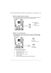
... jumper on the AC. 6. Remove AC power line. 2. Reset your desired password or clear the CMOS data. 17 Set the jumper to avoid damaging the motherboard. 13 Pin 1-2 Close: Normal Operation (default). 13 13 Pin 2-3 Close: Clear CMOS data. ※ Clear CMOS Procedures: 1. Wait for five seconds. 4. Set the .... Power on pin2-3, it allows user to restore the BIOS safe setting and the CMOS data, please carefully follow the procedures to "Pin 2-3 close ". 5. A780G M2+ SE/A780V M2+ SE/A740G M2+ SE JCDIN1: CD-ROM Audio-in Connector This connector allows user to "Pin 1-2 close ". 3.
... jumper on the AC. 6. Remove AC power line. 2. Reset your desired password or clear the CMOS data. 17 Set the jumper to avoid damaging the motherboard. 13 Pin 1-2 Close: Normal Operation (default). 13 13 Pin 2-3 Close: Clear CMOS data. ※ Clear CMOS Procedures: 1. Wait for five seconds. 4. Set the .... Power on pin2-3, it allows user to restore the BIOS safe setting and the CMOS data, please carefully follow the procedures to "Pin 2-3 close ". 5. A780G M2+ SE/A780V M2+ SE/A740G M2+ SE JCDIN1: CD-ROM Audio-in Connector This connector allows user to "Pin 1-2 close ". 3.

Setup Manual
Page 20
... 17 Data 7 18 Ground 19 -ACK 20 Ground 21 Busy 22 Ground 23 PE 24 Ground 25 SCLT 26 Key JCOM1: Serial port Connector The motherboard has a Serial Port Connector for connecting RS-232 Port. Motherboard Manual JPRNT1: Printer Port Connector This header allows you to send 9 Ring indicator 10 NC 1 9 18
... 17 Data 7 18 Ground 19 -ACK 20 Ground 21 Busy 22 Ground 23 PE 24 Ground 25 SCLT 26 Key JCOM1: Serial port Connector The motherboard has a Serial Port Connector for connecting RS-232 Port. Motherboard Manual JPRNT1: Printer Port Connector This header allows you to send 9 Ring indicator 10 NC 1 9 18

Setup Manual
Page 22
A power supply above 450W is seated into PEX16_1. Motherboard Manual CHAPTER 4: HYBRID CROSSFIREX FUNCTION (FOR A780G M2+ SE/A780V M2+ SE) 4.1 HYBRID CROSSFIREX REQUIREMENTS Only Windows Vista supports Hybrid CrossFireX function. A graphics card with Radeon HD3450/HD3470 GPU. PEX16_1 Rade on HD3450 Rade on HD3470 Notice: ...
A power supply above 450W is seated into PEX16_1. Motherboard Manual CHAPTER 4: HYBRID CROSSFIREX FUNCTION (FOR A780G M2+ SE/A780V M2+ SE) 4.1 HYBRID CROSSFIREX REQUIREMENTS Only Windows Vista supports Hybrid CrossFireX function. A graphics card with Radeon HD3450/HD3470 GPU. PEX16_1 Rade on HD3450 Rade on HD3470 Notice: ...

Setup Manual
Page 24
... volume or drive is corrupted or becomes unavailable because of the data can be applied for small databases or any other drive. - Should one drive. Motherboard Manual RAID 1: Every read and write is actually carried out in parallel across 2 disk drives in the array.
... volume or drive is corrupted or becomes unavailable because of the data can be applied for small databases or any other drive. - Should one drive. Motherboard Manual RAID 1: Every read and write is actually carried out in parallel across 2 disk drives in the array.
Setup Manual
Page 26
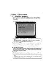
...Driver Installation To install the driver, please click on the Software icon. The setup guide will list the software available for your motherboard and operating system. Note: You will list the compatible driver for your system, click on each device driver to launch the ... Click on each software title to locate and execute the file SETUP.EXE under your optical drive. You will auto detect your motherboard and operating system. A. Motherboard Manual CHAPTER 6: USEFUL HELP 6.1 DRIVER INSTALLATION NOTE After you installed your operating system, please insert the Fully Setup Driver CD ...
...Driver Installation To install the driver, please click on the Software icon. The setup guide will list the software available for your motherboard and operating system. Note: You will list the compatible driver for your system, click on each device driver to launch the ... Click on each software title to locate and execute the file SETUP.EXE under your optical drive. You will auto detect your motherboard and operating system. A. Motherboard Manual CHAPTER 6: USEFUL HELP 6.1 DRIVER INSTALLATION NOTE After you installed your operating system, please insert the Fully Setup Driver CD ...

Setup Manual
Page 28
...with other third parties, so please feel free to the following web http://www.biostar.com.tw/app/en-us/about/contact.php for your system information while using Outlook Express as your system information including motherboard/BIOS/CPU/video/ device/OS information. We will be saved to enter file name... contact information. 26 This information is also concluded in the sent mail. click "Send" to confirm or "Do Not Send" to send the mail out. Motherboard Manual After filling up this information to a .txt file, click "Save As..." Open the saved .txt file, you to a .txt file. If you...
...with other third parties, so please feel free to the following web http://www.biostar.com.tw/app/en-us/about/contact.php for your system information while using Outlook Express as your system information including motherboard/BIOS/CPU/video/ device/OS information. We will be saved to enter file name... contact information. 26 This information is also concluded in the sent mail. click "Send" to confirm or "Do Not Send" to send the mail out. Motherboard Manual After filling up this information to a .txt file, click "Save As..." Open the saved .txt file, you to a .txt file. If you...
Setup Manual
Page 29
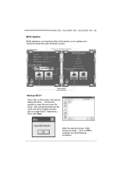
... for AWARD BIOS) Save current BIOS to update your motherboard BIOS under Windows system. Click on this button, the saving dialog will show . Choose the position to complete the BIOS Backup procedure. 27 After the saving process, finish dialog will show . A780G M2+ SE/A780V M2+ SE/A740G M2+ SE BIOS Update BIOS Update is a convenient utility which...
... for AWARD BIOS) Save current BIOS to update your motherboard BIOS under Windows system. Click on this button, the saving dialog will show . Choose the position to complete the BIOS Backup procedure. 27 After the saving process, finish dialog will show . A780G M2+ SE/A780V M2+ SE/A740G M2+ SE BIOS Update BIOS Update is a convenient utility which...

Setup Manual
Page 30
... other applications during this procedure. In the BIOS setup, use the Load Optimized Defaults function and then Save and Exit Setup to enter BIOS setup. Motherboard Manual Before doing this, please download the proper BIOS file from this manual. 28 or click No to the Backup BIOS procedure; After the BIOS...
... other applications during this procedure. In the BIOS setup, use the Load Optimized Defaults function and then Save and Exit Setup to enter BIOS setup. Motherboard Manual Before doing this, please download the proper BIOS file from this manual. 28 or click No to the Backup BIOS procedure; After the BIOS...

