

Installation Handbook
Page 2
... implied, with respect to the contents hereof and specifically disclaims any warranties, merchantability or fitness for any particular purpose. All rights reserved. Further, BenQ Corporation reserves the right to revise this publication may be reproduced, transmitted, transcribed, stored in a retrieval system or translated into any language or... the prior written permission of such revision or changes. 2 Copyright Copyright © 2020 by any means, electronic, mechanical, magnetic, optical, chemical, manual or otherwise, without obligation of BenQ Corporation to notify any person of...
... implied, with respect to the contents hereof and specifically disclaims any warranties, merchantability or fitness for any particular purpose. All rights reserved. Further, BenQ Corporation reserves the right to revise this publication may be reproduced, transmitted, transcribed, stored in a retrieval system or translated into any language or... the prior written permission of such revision or changes. 2 Copyright Copyright © 2020 by any means, electronic, mechanical, magnetic, optical, chemical, manual or otherwise, without obligation of BenQ Corporation to notify any person of...

Installation Handbook
Page 5
.... Notes on the back of this Installation Handbook are held. At the end of the display. Display installation guide To ensure safety, please read this manual carefully before performing a new installation.
.... Notes on the back of this Installation Handbook are held. At the end of the display. Display installation guide To ensure safety, please read this manual carefully before performing a new installation.

Installation Handbook
Page 10
...extension guide This guide provides additional information about how to extend VGA, HDMI and USB connections as required in this guide and the User Manual of the cable. • Ensure that incorrect connections may adversely affect picture quality. • Do not remove cables from the ports ...cables and signal amplifiers/repeaters. • Familiarize yourself with the ports and sockets on the display and the devices you set up your BenQ display to ensure stable and optimal performance. Pay attention to connect. Refer to the instructions in the environment where you want to the...
...extension guide This guide provides additional information about how to extend VGA, HDMI and USB connections as required in this guide and the User Manual of the cable. • Ensure that incorrect connections may adversely affect picture quality. • Do not remove cables from the ports ...cables and signal amplifiers/repeaters. • Familiarize yourself with the ports and sockets on the display and the devices you set up your BenQ display to ensure stable and optimal performance. Pay attention to connect. Refer to the instructions in the environment where you want to the...

Installation Handbook
Page 11
Connect the VGA input jack on the display to the User Manual of your display for the location of VGA and corresponding audio input jacks. • The audio cable, VGA signal amplifier/repeater and additional VGA cable ...
Connect the VGA input jack on the display to the User Manual of your display for the location of VGA and corresponding audio input jacks. • The audio cable, VGA signal amplifier/repeater and additional VGA cable ...

Installation Handbook
Page 12
... the HDMI cable), in order to prevent potential display quality problems like interference and ghosting, if you need to connect the display to the User Manual of your display for the location of HDMI input jacks. • The HDMI cables and HDMI signal amplifier/repeater are not supplied and should be...
... the HDMI cable), in order to prevent potential display quality problems like interference and ghosting, if you need to connect the display to the User Manual of your display for the location of HDMI input jacks. • The HDMI cables and HDMI signal amplifier/repeater are not supplied and should be...

Installation Handbook
Page 13
.... 2. Connecting faceplate 1. Connect the mini-B plug of the supplied USB cable to the USB Mini-B port on page 14. Connect the computer to the User Manual of your display for the location of USB port. • Any cable used in prior installations for other displays and projectors in the same location...
.... 2. Connecting faceplate 1. Connect the mini-B plug of the supplied USB cable to the USB Mini-B port on page 14. Connect the computer to the User Manual of your display for the location of USB port. • Any cable used in prior installations for other displays and projectors in the same location...

Installation Handbook
Page 14
... USB extension cable may be different from the description above. Display USB port USB cable Active USB extension cable Computer • Refer to the User Manual of your display for the connected USB device. 1. Extending USB connection using an active (powered) USB extension cable You can use a commercially available active (powered...
... USB extension cable may be different from the description above. Display USB port USB cable Active USB extension cable Computer • Refer to the User Manual of your display for the connected USB device. 1. Extending USB connection using an active (powered) USB extension cable You can use a commercially available active (powered...

Installation Handbook
Page 15
... cable to avoid electronic interference. Display USB port USB cable USB-CAT converter Category 5/5e/6 network cable USB cable Computer • Refer to the User Manual of your display for the maximum length of the Category 5/5e/6 network cable. • The type of USB port. • Refer to the USB port...
... cable to avoid electronic interference. Display USB port USB cable USB-CAT converter Category 5/5e/6 network cable USB cable Computer • Refer to the User Manual of your display for the maximum length of the Category 5/5e/6 network cable. • The type of USB port. • Refer to the USB port...

Installation Handbook
Page 16
... display, and the type-A plug of the USB cables used to connect the display to the active USB extension cable and computer to the User Manual of your display for the location of USB port. • For best results, use an active (powered) USB-CAT converter to the USB type-A port...
... display, and the type-A plug of the USB cables used to connect the display to the active USB extension cable and computer to the User Manual of your display for the location of USB port. • For best results, use an active (powered) USB-CAT converter to the USB type-A port...

Installation Handbook
Page 21
...weight. See Checking the safe distance between displays on the mounting bracket or stand by tightening the screws through the direct transfer of this manual carefully before performing a new installation. Mount and fasten the display on page 23. 3. Video wall installation guide To ensure safety, ...8226; The video wall must be damaged by hand before installation and follow the instructions herein. Refer to the wall following the instruction manual of glass which is strong enough to bear its weight. • If the video wall is mounted with cushions during installation. Install ...
...weight. See Checking the safe distance between displays on the mounting bracket or stand by tightening the screws through the direct transfer of this manual carefully before performing a new installation. Mount and fasten the display on page 23. 3. Video wall installation guide To ensure safety, ...8226; The video wall must be damaged by hand before installation and follow the instructions herein. Refer to the wall following the instruction manual of glass which is strong enough to bear its weight. • If the video wall is mounted with cushions during installation. Install ...
Installation Handbook
Page 28
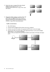
.... (in) (out) (in) (out) (in) (in) (out) 28 Video wall installation guide Connect the first display with the video source (e.g. Follow Step 2 ~ 3 to the user manual of the purchased model for the location of the cable to the appropriate OUT port on the second display. Cable connections 1. computer). 3. Connect the other...
.... (in) (out) (in) (out) (in) (in) (out) 28 Video wall installation guide Connect the first display with the video source (e.g. Follow Step 2 ~ 3 to the user manual of the purchased model for the location of the cable to the appropriate OUT port on the second display. Cable connections 1. computer). 3. Connect the other...
Installation Handbook
Page 29
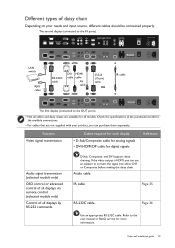
Page 36 Use an appropriate RS-232C cable. Refer to the user manual or BenQ service for the available connections. • For cables that are available for digital signals Reference Audio signal transmission (selected models only) OSD control or advanced ...
Page 36 Use an appropriate RS-232C cable. Refer to the user manual or BenQ service for the available connections. • For cables that are available for digital signals Reference Audio signal transmission (selected models only) OSD control or advanced ...

Installation Handbook
Page 35
... just connected within the motion range. 4. Management by remote control, RS-232 commands, or LAN control. Video wall installation guide 35 Refer to the user manual of remote control. 5. Managing the daisy chain: PL460/PH460/PL550/PH550 Once the displays have been daisy chained and the position and ID numbers have...
... just connected within the motion range. 4. Management by remote control, RS-232 commands, or LAN control. Video wall installation guide 35 Refer to the user manual of remote control. 5. Managing the daisy chain: PL460/PH460/PL550/PH550 Once the displays have been daisy chained and the position and ID numbers have...

Installation Handbook
Page 36
... separately if not supplied). 3. RS-232C cable • Use an appropriate RS-232C cable. Management by receiving RS-232 commands from the BenQ local website) for each display. Now the computer and all displays separately to Setting > Control Setting each display. See Setting the ID number...null modem cables (purchased separately if not supplied). 4. Make sure the ID number has been set . Connect the computer to the user manual or BenQ service for more information. • For PL490/PL552/PL553/PH5501/PH5502, choose the RS232 control form Card OPS or embedded RS232 in ...
... separately if not supplied). 3. RS-232C cable • Use an appropriate RS-232C cable. Management by receiving RS-232 commands from the BenQ local website) for each display. Now the computer and all displays separately to Setting > Control Setting each display. See Setting the ID number...null modem cables (purchased separately if not supplied). 4. Make sure the ID number has been set . Connect the computer to the user manual or BenQ service for more information. • For PL490/PL552/PL553/PH5501/PH5502, choose the RS232 control form Card OPS or embedded RS232 in ...
Installation Handbook
Page 37
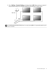
RJ45 cable LAN switch or hub For PL490/PL552/PL553/PH5501/PH5502, there is no need to the user manual of the purchased model for the detailed settings and the operation of LAN control. Refer to select LAN as it is automatically enabled once the device is connected. Video wall installation guide 37 4. Select LAN. Go to Setting > Control Setting each display.
RJ45 cable LAN switch or hub For PL490/PL552/PL553/PH5501/PH5502, there is no need to the user manual of the purchased model for the detailed settings and the operation of LAN control. Refer to select LAN as it is automatically enabled once the device is connected. Video wall installation guide 37 4. Select LAN. Go to Setting > Control Setting each display.
Installation Handbook
Page 38
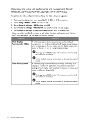
... service center for demonstration videos if needed . 38 Video wall installation guide Go to On. 3. Go to the user manual or BenQ service for each display easily on delay and set it to fully utilize the video wall management. Go to General settings > Switch on a host computer, ...
... service center for demonstration videos if needed . 38 Video wall installation guide Go to On. 3. Go to the user manual or BenQ service for each display easily on delay and set it to fully utilize the video wall management. Go to General settings > Switch on a host computer, ...

Installation Handbook
Page 42
... for M4 screw. 2. There are two loops of screw holes (outer & inner), depend on the design of each model. (Please check the user manual for using loop information) • Outer loop: Big screw holes for M6 screw. • Inner loop: Small screw holes for PL552/PL553/PH5501/ PH5502 ...; M6 screw: for PL552/PL553/PH5501/ PH5502 • M4 screw: for M4 screw. 2. There are two loops of each model. (Please check the user manual for using loop information) • Outer loop: Big screw holes for M6 screw. • Inner loop: Small screw holes for PL490 • Using "Edge...
... for M4 screw. 2. There are two loops of screw holes (outer & inner), depend on the design of each model. (Please check the user manual for using loop information) • Outer loop: Big screw holes for M6 screw. • Inner loop: Small screw holes for PL552/PL553/PH5501/ PH5502 ...; M6 screw: for PL552/PL553/PH5501/ PH5502 • M4 screw: for M4 screw. 2. There are two loops of each model. (Please check the user manual for using loop information) • Outer loop: Big screw holes for M6 screw. • Inner loop: Small screw holes for PL490 • Using "Edge...

Installation Handbook
Page 45
Video wall installation guide 45 Setting the display position for special video wall layout If a special layout is requested, you will need an additional software and device (purchased separately) for more information. Refer to the user manual of the purchased software for advanced settings.
Video wall installation guide 45 Setting the display position for special video wall layout If a special layout is requested, you will need an additional software and device (purchased separately) for more information. Refer to the user manual of the purchased software for advanced settings.

Installation Handbook
Page 65
Re-connect the power cord. See the user manual for signal input. • Go to Picture > Noise Reduction. • Move the display to another location to see if the interference is used for details. ... the input source is not Depending on the selected input, connect the display with another graphic card (GPU). The main board could be Contact the BenQ authorized service partner for damaged. The image has a faulty coloration. display. Possible causes Possible solutions The video cable is not connected Make sure the video...
Re-connect the power cord. See the user manual for signal input. • Go to Picture > Noise Reduction. • Move the display to another location to see if the interference is used for details. ... the input source is not Depending on the selected input, connect the display with another graphic card (GPU). The main board could be Contact the BenQ authorized service partner for damaged. The image has a faulty coloration. display. Possible causes Possible solutions The video cable is not connected Make sure the video...

Installation Handbook
Page 66
Refer to the user manual for stretched on the menu options. Note the picture may appear distorted or Go to Screen > Aspect to the screen. You are running at its ...
Refer to the user manual for stretched on the menu options. Note the picture may appear distorted or Go to Screen > Aspect to the screen. You are running at its ...

