Service Guide
Page 9
... This chapter lists the specifications and section names of the film scanner. 2.1 Specifications Machine Type Professional film scanner Scan Method 3 pass , color CCD Scan Mode grayscale 12 bits/pixel (4096 levels of gray) color 48 bits/pixel (over 68.7 billion colors) Optical Resolution 2700 × 2700 dpi Scanning Area Slide: 35mm mounted size (Max. batch scan 4 units) Filmstrip 35mm size (Max. batch scan 6 units) Interface SCSI II Scan Velocity Calibration Color: 5 sec Scan Speed Color: less then 10ms/line, less...
... This chapter lists the specifications and section names of the film scanner. 2.1 Specifications Machine Type Professional film scanner Scan Method 3 pass , color CCD Scan Mode grayscale 12 bits/pixel (4096 levels of gray) color 48 bits/pixel (over 68.7 billion colors) Optical Resolution 2700 × 2700 dpi Scanning Area Slide: 35mm mounted size (Max. batch scan 4 units) Filmstrip 35mm size (Max. batch scan 6 units) Interface SCSI II Scan Velocity Calibration Color: 5 sec Scan Speed Color: less then 10ms/line, less...

Service Guide
Page 16
Then the images are supplied with film scanner: filmstrip and slide holders. 3.2.2 Auto-Focus First the holder will do your scanning. 3-2 API Confidential Theory of holders are shown on the screen. 3.2.4 Pick Target Pick the desired scanning area and position. In addition, you can choose scanning condition, such as scan types (color or gray), resolution (DPI), hi-light...etc. Two types of Operation No Copy/Reproduction allowed You...
Then the images are supplied with film scanner: filmstrip and slide holders. 3.2.2 Auto-Focus First the holder will do your scanning. 3-2 API Confidential Theory of holders are shown on the screen. 3.2.4 Pick Target Pick the desired scanning area and position. In addition, you can choose scanning condition, such as scan types (color or gray), resolution (DPI), hi-light...etc. Two types of Operation No Copy/Reproduction allowed You...

Service Guide
Page 23
... 6 parts : ASIC Scanner Controller, Analog Circuits, CCD Module, Power supply and Inverter,, ICE Function and other Elements (including line motor, home sensor, Lamp...etc). Chapter 5 Electrical Systems 5.1 Overview The overview of electrical systems of film scanner is shown in figure 5-2. Through functional partitions, the whole scanner system can be divided into 3 main modules as shown in Figure 5-1. Power Board Host Computer SCSI Interface Cable...
... 6 parts : ASIC Scanner Controller, Analog Circuits, CCD Module, Power supply and Inverter,, ICE Function and other Elements (including line motor, home sensor, Lamp...etc). Chapter 5 Electrical Systems 5.1 Overview The overview of electrical systems of film scanner is shown in figure 5-2. Through functional partitions, the whole scanner system can be divided into 3 main modules as shown in Figure 5-1. Power Board Host Computer SCSI Interface Cable...

Service Guide
Page 24
... get the digitized data. These digitized pixels are captured from both the ICE Function and Lamp. The image is passed through lens and into the memory, which is controlled by the differential operational amplifier. This module is located at CCD module, which is managed 5-2 API Confidential Electrical Systems No Copy/Reproduction allowed The main module is composed of the 2740S scanner. The I /O Module Figure 5-2 Film Scanner...
... get the digitized data. These digitized pixels are captured from both the ICE Function and Lamp. The image is passed through lens and into the memory, which is controlled by the differential operational amplifier. This module is located at CCD module, which is managed 5-2 API Confidential Electrical Systems No Copy/Reproduction allowed The main module is composed of the 2740S scanner. The I /O Module Figure 5-2 Film Scanner...

Service Guide
Page 25
... (ASIC scanner controller) and by a single-chip microprocessor: W78E516B which is compatible with every scan-line. AC 100~240V Power Board 5V 12V 12V 16V Main Board Figure 5-3 Film Scanner Power Board. It has multiple DC outputs: +5V, +12V, and +16V. If a color image is requested, the color CCD is co-operated with 8052. It integrates a DC/AC inverter into the required power sources. Please...
... (ASIC scanner controller) and by a single-chip microprocessor: W78E516B which is compatible with every scan-line. AC 100~240V Power Board 5V 12V 12V 16V Main Board Figure 5-3 Film Scanner Power Board. It has multiple DC outputs: +5V, +12V, and +16V. If a color image is requested, the color CCD is co-operated with 8052. It integrates a DC/AC inverter into the required power sources. Please...
Service Guide
Page 26
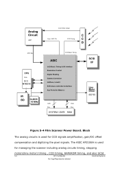
... SCSI slave controller & interface Aux Ports( for CCD signals amplification, gain/DC offset compensation and digitizing the pixel signals. Block The analog circuits is used for Motors ) Addr. Bus Data Bus SYSTEM / DATA RAM SCSI I/F Line Motor Driver (6219) Figure 5-4 Film Scanner Power Board. The ASIC AP2106A is used for managing the scanner including analog circuits timing, stepping motors(line motor) timing , CCD timing, RAM/ROM timing...
... SCSI slave controller & interface Aux Ports( for CCD signals amplification, gain/DC offset compensation and digitizing the pixel signals. Block The analog circuits is used for Motors ) Addr. Bus Data Bus SYSTEM / DATA RAM SCSI I/F Line Motor Driver (6219) Figure 5-4 Film Scanner Power Board. The ASIC AP2106A is used for managing the scanner including analog circuits timing, stepping motors(line motor) timing , CCD timing, RAM/ROM timing...

Service Guide
Page 27
... the handshaking, software protocols, and interfacing SCSI bus. During preparing and scanning, it to direct connection the SCSI bus.This section describes the SCSI Interface. The SCSI interface is built in figure 5-5. To scan an image, the host computer sends a series of the following items: a host SCSI adapter card(ACARD 6710-D, for both PC and Mac, is achieved via SCSI interface. 5.2 SCSI Interface The 2740S scanner SCSI protocol is...
... the handshaking, software protocols, and interfacing SCSI bus. During preparing and scanning, it to direct connection the SCSI bus.This section describes the SCSI Interface. The SCSI interface is built in figure 5-5. To scan an image, the host computer sends a series of the following items: a host SCSI adapter card(ACARD 6710-D, for both PC and Mac, is achieved via SCSI interface. 5.2 SCSI Interface The 2740S scanner SCSI protocol is...
Service Guide
Page 31
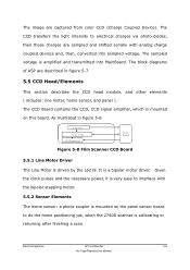
... home sensor: a photo-coupler is mounted on this board. Given the clock pulses and the necessary power, it is very easy to do the home positioning job, when the 2740S scanner is a bipolar motor driver. It is calibrating or returning after finishing a scan. The sampled voltage is mounted on the panel sensor board to interface with analog charge coupled devices and...
... home sensor: a photo-coupler is mounted on this board. Given the clock pulses and the necessary power, it is very easy to do the home positioning job, when the 2740S scanner is a bipolar motor driver. It is calibrating or returning after finishing a scan. The sampled voltage is mounted on the panel sensor board to interface with analog charge coupled devices and...

Service Guide
Page 32
... 3. multi bit and single bit 6. brightness 2. contrast 3. window mode 7. matrix operation Send scanned data (* control scanning timing and handshaking timing *) End of scan Next scan Stop (power-off) Figure 5-10 Main Flow Chart of Film Scanner Start (power-on the CCD board in 2740S scanner (referring to host "START SCAN" command Calibration Adjust scanning parameters: 1. Initial system and CPU parameter 2. gamma correction 5. shadow-highlight 4. line art and halftone 8. test ROM 2. test CCD and lamp 5. 5.5.3 CCD/Home Sensor...
... 3. multi bit and single bit 6. brightness 2. contrast 3. window mode 7. matrix operation Send scanned data (* control scanning timing and handshaking timing *) End of scan Next scan Stop (power-off) Figure 5-10 Main Flow Chart of Film Scanner Start (power-on the CCD board in 2740S scanner (referring to host "START SCAN" command Calibration Adjust scanning parameters: 1. Initial system and CPU parameter 2. gamma correction 5. shadow-highlight 4. line art and halftone 8. test ROM 2. test CCD and lamp 5. 5.5.3 CCD/Home Sensor...

Service Guide
Page 41
... film scanner. 7.1 Precaution Make sure that you unplug the film scanner before disassembling. Never turn the power on if there is disassembled, pay special attention to the following: A. CAUTION: Make sure there is not a strip holder or slide holder inserted Maintenance API Confidential 7-1 No Copy/Reproduction allowed Do not disassemble the CCD board and lens. Remove the two screws in the adapter cord and operate...
... film scanner. 7.1 Precaution Make sure that you unplug the film scanner before disassembling. Never turn the power on if there is disassembled, pay special attention to the following: A. CAUTION: Make sure there is not a strip holder or slide holder inserted Maintenance API Confidential 7-1 No Copy/Reproduction allowed Do not disassemble the CCD board and lens. Remove the two screws in the adapter cord and operate...

Service Guide
Page 48
... by vertical scanning lines will be affected but also the output image may be formed precisely on the lensbox. (3) CCD The CCD's position is the decisive factor for the image management. It owns a precise position while the calibration is out of the range, not only the resolution will likely be twisted. 7-8 API Confidential Maintenance No Copy/Reproduction allowed...
... by vertical scanning lines will be affected but also the output image may be formed precisely on the lensbox. (3) CCD The CCD's position is the decisive factor for the image management. It owns a precise position while the calibration is out of the range, not only the resolution will likely be twisted. 7-8 API Confidential Maintenance No Copy/Reproduction allowed...

Service Guide
Page 49
... hard disk storage space can be used as data swapping once the memory is not enough. (2) Display Capability A true-color display card that supports more than 24-bit colors could produce superior color images. After 15 minutes' pending, the system would happen if I do not use the true color card? Q: What would shut up the light indicating it is the minimum hardware configuration required for using a scanner? You...
... hard disk storage space can be used as data swapping once the memory is not enough. (2) Display Capability A true-color display card that supports more than 24-bit colors could produce superior color images. After 15 minutes' pending, the system would happen if I do not use the true color card? Q: What would shut up the light indicating it is the minimum hardware configuration required for using a scanner? You...
Service Guide
Page 50
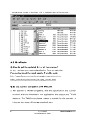
... updated driver of hardware and software. A.2 MiraPhoto Q: How to integrate the power of the scanner? A: You can work with TWAIN? With this specification, the scanner can have our most updated driver from our web-site: Please download the most update from the web: http://www.Benq.com.tw/global/service/scan/drivers.htm http://www.Benq.com/drivers/imaging_drivers.html Q: Is the scanner compatible with any Windows or Mac applications that support the TWAIN standard. image data...
... updated driver of hardware and software. A.2 MiraPhoto Q: How to integrate the power of the scanner? A: You can work with TWAIN? With this specification, the scanner can have our most updated driver from our web-site: Please download the most update from the web: http://www.Benq.com.tw/global/service/scan/drivers.htm http://www.Benq.com/drivers/imaging_drivers.html Q: Is the scanner compatible with any Windows or Mac applications that support the TWAIN standard. image data...
Service Guide
Page 51
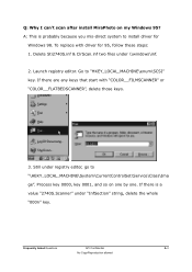
... keys that start with driver for Windows 98. A: This is a value "2740S.Scanner" under registry editor, go to "\HEKY_LOCAL_MACHINE\System\CurrentControlSet\Service\Class\Ima ge". Frequently Asked Questions API Confidential A-3 No Copy/Reproduction allowed Delete Sti2740S.inf & ClrScan.inf two files under \\windows\inf. 2. Process key 0000, key 0001, and so on my Windows 95? Q: Why I can't scan after install MiraPhoto...
... keys that start with driver for Windows 98. A: This is a value "2740S.Scanner" under registry editor, go to "\HEKY_LOCAL_MACHINE\System\CurrentControlSet\Service\Class\Ima ge". Frequently Asked Questions API Confidential A-3 No Copy/Reproduction allowed Delete Sti2740S.inf & ClrScan.inf two files under \\windows\inf. 2. Process key 0000, key 0001, and so on my Windows 95? Q: Why I can't scan after install MiraPhoto...
Service Guide
Page 53
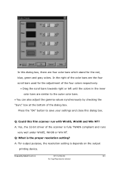
... values synchronously by checking the "Sync" box at the bottom of the dialog box. Q: What is depends on the output printing device. Q: Could this film scanner run with Win95, Win98 and Win NT? In the right of the color bars are the four scroll bars used for the red, blue, green and gray colors. A: Yes, the 32-bit driver of the four colors respectively. •...
... values synchronously by checking the "Sync" box at the bottom of the dialog box. Q: What is depends on the output printing device. Q: Could this film scanner run with Win95, Win98 and Win NT? In the right of the color bars are the four scroll bars used for the red, blue, green and gray colors. A: Yes, the 32-bit driver of the four colors respectively. •...
Service Guide
Page 54
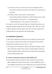
... config supper IO chip and change its default setting. To scan at higher resolution than the proper value does not do any good to other SCSI card? A: Just install the SCSI card driver first, then install the scanner driver. (1) Continuous tone color printer (such as dye-sublimation printer) The scanning resolution should be 180 dpi (180 = 360 /2). The general idea is extreme slow on both the gray level...
... config supper IO chip and change its default setting. To scan at higher resolution than the proper value does not do any good to other SCSI card? A: Just install the SCSI card driver first, then install the scanner driver. (1) Continuous tone color printer (such as dye-sublimation printer) The scanning resolution should be 180 dpi (180 = 360 /2). The general idea is extreme slow on both the gray level...
Service Guide
Page 55
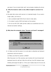
... select "do not install SCSI card" and complete installing the driver. Q: Why the Scanner cable is better to add a SCSI terminator at all, Frequently Asked Questions API Confidential A-7 No Copy/Reproduction allowed After the self test, the LED indicator stops blinking and keeps the light on of the scanner, scan module will move at the scanner. 3. After the power on . Do not use RS-232C cable (printer cable) as a substitute...
... select "do not install SCSI card" and complete installing the driver. Q: Why the Scanner cable is better to add a SCSI terminator at all, Frequently Asked Questions API Confidential A-7 No Copy/Reproduction allowed After the self test, the LED indicator stops blinking and keeps the light on of the scanner, scan module will move at the scanner. 3. After the power on . Do not use RS-232C cable (printer cable) as a substitute...
Service Guide
Page 56
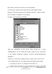
... windows ("Control Panel\System\Device Manager"). After the installation of the "Color Flatbed Scanner_10", please check the following few things: If scanner is installed. Please check the cable is at unlock position. (3) If the scan module moves twice and the LED indicator keeps blinking, the scanner likely has the hardware problem. Please contact the local dealer or supplier for 2740s film scanner under the icon "Scanners" in front of the driver...
... windows ("Control Panel\System\Device Manager"). After the installation of the "Color Flatbed Scanner_10", please check the following few things: If scanner is installed. Please check the cable is at unlock position. (3) If the scan module moves twice and the LED indicator keeps blinking, the scanner likely has the hardware problem. Please contact the local dealer or supplier for 2740s film scanner under the icon "Scanners" in front of the driver...

Service Guide
Page 57
... by warranty card, so you power on the Scanner before booting Windows. Be sure that bundle with scanner is some of their on the "SCSI Controllers" and then click the "Refresh" button and the "scanners" section will cause the CD hard to register. A: Because the scanner quality is no "scanners" section in Device Manager, Please Click the "EPPSCSI Miniport Driver Vx.x" on -line documentation to readable...
... by warranty card, so you power on the Scanner before booting Windows. Be sure that bundle with scanner is some of their on the "SCSI Controllers" and then click the "Refresh" button and the "scanners" section will cause the CD hard to register. A: Because the scanner quality is no "scanners" section in Device Manager, Please Click the "EPPSCSI Miniport Driver Vx.x" on -line documentation to readable...
Service Guide
Page 60
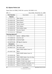
... Copy/Reproduction allowed B.2 Spare Parts List Spare Parts for BENQ 2740S film scanner (99.S0661.X1X) REV.: 0 Part Number Module 55.S0601.001 55.61602.001 55.61604.001 55.61605.001 57.61624.001 25.30023.001 55.61606.001 55.S0606.001 Issue Date: November 23, 2000 Description Comment Main Board Power Board Panel Board Sensor Board CCD Module Cold Cathod Lamp...
... Copy/Reproduction allowed B.2 Spare Parts List Spare Parts for BENQ 2740S film scanner (99.S0661.X1X) REV.: 0 Part Number Module 55.S0601.001 55.61602.001 55.61604.001 55.61605.001 57.61624.001 25.30023.001 55.61606.001 55.S0606.001 Issue Date: November 23, 2000 Description Comment Main Board Power Board Panel Board Sensor Board CCD Module Cold Cathod Lamp...


