Manual
Page 2
Repairs should be operated in the accompanying literature. ULTRALINK UL2000M IMPORTANT SAFETY INSTRUCTIONS CAUTION: To reduce the risk of electric shock do not perform any way, such as power supply cord or plug is used, use caution when ...use this apparatus near any ventilation openings. No user serviceable parts inside the enclosure-voltage that may be done by the manufacturer, or sold with liquids, such as radiators, heat registers, stoves, or other than that produce heat. 9) Protect the power cord from being walked on the apparatus. Please read the manual...
Repairs should be operated in the accompanying literature. ULTRALINK UL2000M IMPORTANT SAFETY INSTRUCTIONS CAUTION: To reduce the risk of electric shock do not perform any way, such as power supply cord or plug is used, use caution when ...use this apparatus near any ventilation openings. No user serviceable parts inside the enclosure-voltage that may be done by the manufacturer, or sold with liquids, such as radiators, heat registers, stoves, or other than that produce heat. 9) Protect the power cord from being walked on the apparatus. Please read the manual...
Manual
Page 3
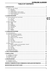
... 3.3.1 Battery condition and transmission channel 16 3.3.2 Transmission frequency 17 3.3.3 Preset ...17 3.3.4 Mic Gain ...17 3.3.5 Auto Mute ...17 3.5 ULM2000 level setting ...17 4. INSTALLATION ...18 5.1 Installation information ...18 5.2 Installation in detail ...8 2.2.1 TUNE ...8 2.2.2 SCAN ...9 2.2.3 SQUELCH ...9 2.2.4 AUTO MUTE ...10 2.2.5 DISPLAY ...10 2.2.6 LOCK ...10 2.2.7 PRESET ...11 3. APPLICATION EXAMPLE 18 5. SPECIFICATIONS ...21 6.1 ULR2000 receiver ...21 6.2 ULM2000 microphone ...22 FEDERAL COMMUNICATIONS COMMISSION COMPLIANCE INFORMATION 23 MICROPHONE QUICK START GUIDE...
... 3.3.1 Battery condition and transmission channel 16 3.3.2 Transmission frequency 17 3.3.3 Preset ...17 3.3.4 Mic Gain ...17 3.3.5 Auto Mute ...17 3.5 ULM2000 level setting ...17 4. INSTALLATION ...18 5.1 Installation information ...18 5.2 Installation in detail ...8 2.2.1 TUNE ...8 2.2.2 SCAN ...9 2.2.3 SQUELCH ...9 2.2.4 AUTO MUTE ...10 2.2.5 DISPLAY ...10 2.2.6 LOCK ...10 2.2.7 PRESET ...11 3. APPLICATION EXAMPLE 18 5. SPECIFICATIONS ...21 6.1 ULR2000 receiver ...21 6.2 ULM2000 microphone ...22 FEDERAL COMMUNICATIONS COMMISSION COMPLIANCE INFORMATION 23 MICROPHONE QUICK START GUIDE...
Manual
Page 4
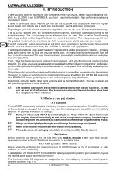
... microphone features a high-quality Panasonic® capsule with 8 permanent, interference-free channels. Beyond that, both units feature other useful functions, such as the transportation company from BEHRINGER leaves you to your local postal/ telecommunication authority! Additional information is available there. 1.1.3 Initial operation of its functions. ULTRALINK UL2000M 1. The IRC compander system guarantees an extremely wide transmission dynamic range...
... microphone features a high-quality Panasonic® capsule with 8 permanent, interference-free channels. Beyond that, both units feature other useful functions, such as the transportation company from BEHRINGER leaves you to your local postal/ telecommunication authority! Additional information is available there. 1.1.3 Initial operation of its functions. ULTRALINK UL2000M 1. The IRC compander system guarantees an extremely wide transmission dynamic range...
Manual
Page 5
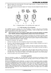
..., using only one or two 9V batteries. When running the unit on the front side of the transmitter-receiver system, change the transmitter (mic) batteries: 1. The plug is to register your new BEHRINGER equipment right after seeing the "LowBat" message. To assure dependable operation of the power supply pressed to blink rapidly. To place the second battery, turn it repaired as...
..., using only one or two 9V batteries. When running the unit on the front side of the transmitter-receiver system, change the transmitter (mic) batteries: 1. The plug is to register your new BEHRINGER equipment right after seeing the "LowBat" message. To assure dependable operation of the power supply pressed to blink rapidly. To place the second battery, turn it repaired as...
Manual
Page 6
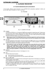
...the mains, please unplug the power supply. If the ULR2000 is in a setup with balanced connections, a maximum signal level of your ULR2000 will be set . for a while. If you set in the display (e.g. frequency, channel number, preset number). ULR2000 RECEIVER Always make sure that high... confirm the values you run the ULR2000 in the basic setting (menu not selected), pressing the UP and the DOWN buttons changes the transmission channel within the selected preset. UP and DOWN These two buttons let you can be using the VOLUME control. ULTRALINK UL2000M 2.
...the mains, please unplug the power supply. If the ULR2000 is in a setup with balanced connections, a maximum signal level of your ULR2000 will be set . for a while. If you set in the display (e.g. frequency, channel number, preset number). ULR2000 RECEIVER Always make sure that high... confirm the values you run the ULR2000 in the basic setting (menu not selected), pressing the UP and the DOWN buttons changes the transmission channel within the selected preset. UP and DOWN These two buttons let you can be using the VOLUME control. ULTRALINK UL2000M 2.
Manual
Page 7
... differentiate between multiple transmitters (set channel. When storing a user-selected frequency in the basic setting (menu not selected), pressing the UP and DOWN buttons changes the transmission channel within the selected preset. ULTRALINK UL2000M COLOR CODE Each BEHRINGER ULTRALINK transmitter can also attach color-coded strips to each receiver. To easily match a transmitter to a receiver, you can be color-coded using the also displays the...
... differentiate between multiple transmitters (set channel. When storing a user-selected frequency in the basic setting (menu not selected), pressing the UP and DOWN buttons changes the transmission channel within the selected preset. ULTRALINK UL2000M COLOR CODE Each BEHRINGER ULTRALINK transmitter can also attach color-coded strips to each receiver. To easily match a transmitter to a receiver, you can be color-coded using the also displays the...

Manual
Page 8
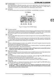
...The power is interrupted (e.g. GND The unit can be earthed. Press the SET button to get to the GND screw. Using the UP and DOWN buttons, the "Frequency" parameter can be modified in 25-kHz increments. 8 2. ULR2000 RECEIVER A matching cable is ...received and demodulated AF starts getting weaker, the noise increases; By using the UP and DOWN buttons you can select various menu items (e.g. Pressing the SET button once gets you into the respective submenu (e.g. Depending on the basic settings of the 8 storage slots in the user preset (Preset 1). ULTRALINK UL2000M...
...The power is interrupted (e.g. GND The unit can be earthed. Press the SET button to get to the GND screw. Using the UP and DOWN buttons, the "Frequency" parameter can be modified in 25-kHz increments. 8 2. ULR2000 RECEIVER A matching cable is ...received and demodulated AF starts getting weaker, the noise increases; By using the UP and DOWN buttons you can select various menu items (e.g. Pressing the SET button once gets you into the respective submenu (e.g. Depending on the basic settings of the 8 storage slots in the user preset (Preset 1). ULTRALINK UL2000M...

Manual
Page 9
... selected. A user-selected frequency is shown in the user preset (Preset 1)! If necessary, the unit automatically switches to this preset. 2.2.2 SCAN Similar to work, the transmitter (e.g. For it is always stored in the display. The display shows the current frequency. 4. As soon...set , press the SET button again. Press the SET button again to get to locate a transmitter). ULTRALINK UL2000M 4. the ULM2000) must be selected by pressing the UP or DOWN buttons. 6. Either press UP or DOWN. If the receiver found the correct frequency, press the SET button again. Press the SET...
... selected. A user-selected frequency is shown in the user preset (Preset 1)! If necessary, the unit automatically switches to this preset. 2.2.2 SCAN Similar to work, the transmitter (e.g. For it is always stored in the display. The display shows the current frequency. 4. As soon...set , press the SET button again. Press the SET button again to get to locate a transmitter). ULTRALINK UL2000M 4. the ULM2000) must be selected by pressing the UP or DOWN buttons. 6. Either press UP or DOWN. If the receiver found the correct frequency, press the SET button again. Press the SET...

Manual
Page 10
... without first muting the receiver, or if the transmission drops out due to weak batteries, audible noise will result. Changing the ULR2000's basic settings 1. Press the SET button again to get to the menu. 2. The display shows the current basic parameter. 4. Press the UP and DOWN buttons once to the menu. 2. ULTRALINK UL2000M 2.2.4 AUTO MUTE If the...
... without first muting the receiver, or if the transmission drops out due to weak batteries, audible noise will result. Changing the ULR2000's basic settings 1. Press the SET button again to get to the menu. 2. The display shows the current basic parameter. 4. Press the UP and DOWN buttons once to the menu. 2. ULTRALINK UL2000M 2.2.4 AUTO MUTE If the...
Manual
Page 11
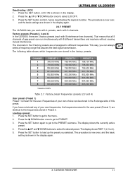
... a frequency range that all assigned to select LOCOFF. 3. LOC ON is meant for the user. The channels in the 3 factory presets are stored in the display. 2. Press the SET button to get to select the desired preset. The display shows the currently active preset. 4. Press the SET button. The display shows PSET 1 (2, 3 or 4). 5. ULTRALINK UL2000M Deactivating...
... a frequency range that all assigned to select LOCOFF. 3. LOC ON is meant for the user. The channels in the 3 factory presets are stored in the display. 2. Press the SET button to get to select the desired preset. The display shows the currently active preset. 4. Press the SET button. The display shows PSET 1 (2, 3 or 4). 5. ULTRALINK UL2000M Deactivating...
Manual
Page 12
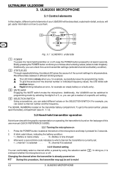
... elements of this user manual (QUICK REFERENCE GUIDE). 3.2.1 Turning the microphone on or off . SELECTION SWITCH Using a screwdriver, you can select a channel number and the frequency. Press the POWER button located at least 2 seconds. Changing the channel when the transmitter is currently set to which channel the transmitter is already powered on the SELECTION SWITCH. ULTRALINK UL2000M 3. Afterward, a second blink code indicates to...
... elements of this user manual (QUICK REFERENCE GUIDE). 3.2.1 Turning the microphone on or off . SELECTION SWITCH Using a screwdriver, you can select a channel number and the frequency. Press the POWER button located at least 2 seconds. Changing the channel when the transmitter is currently set to which channel the transmitter is already powered on the SELECTION SWITCH. ULTRALINK UL2000M 3. Afterward, a second blink code indicates to...
Manual
Page 13
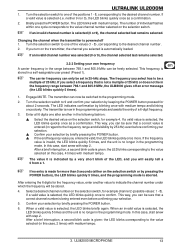
...Setting your selection. 5. The frequency you can only be a multiple of the positions 1 - 8, corresponding to the value/channel number selected on the selection switch, for more . After a brief interruption, a second blink code is selected, the LED blinks quickly once as a confirmation. 2. ULTRALINK UL2000M...the LED blinks corresponding to be set in the programming mode. The value 0 is powered off an error message (the LED blinks quickly 5 times). 1. Changing the channel when the transmitter is indicated by keeping the POWER button pressed for example channel 2...
...Setting your selection. 5. The frequency you can only be a multiple of the positions 1 - 8, corresponding to the value/channel number selected on the selection switch, for more . After a brief interruption, a second blink code is selected, the LED blinks quickly once as a confirmation. 2. ULTRALINK UL2000M...the LED blinks corresponding to be set in the programming mode. The value 0 is powered off an error message (the LED blinks quickly 5 times). 1. Changing the channel when the transmitter is indicated by keeping the POWER button pressed for example channel 2...
Manual
Page 14
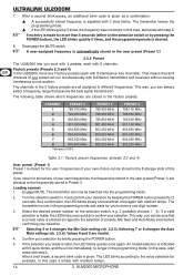
.... 8. Selecting 5 or 6 changes the Mic Gain setting (ch. 3.2.5). Confirm your own choice can be sure that assures the best signal transmission. After a brief break, a second blink code is automatically stored in the 8 storage slots of your selection by keeping the POWER button pressed for 2 seconds. In this case 3 times) with medium tempo. A user-assigned frequency is given...
.... 8. Selecting 5 or 6 changes the Mic Gain setting (ch. 3.2.5). Confirm your own choice can be sure that assures the best signal transmission. After a brief break, a second blink code is automatically stored in the 8 storage slots of your selection by keeping the POWER button pressed for 2 seconds. In this case 3 times) with medium tempo. A user-assigned frequency is given...
Manual
Page 15
...the receiver, or if the transmission fails due to battery charge being transmitted. Engage MUTE. If the selection you talk very softly into the programming mode. 2. Low Gain: the LED blinks once with step 2. 7. Selecting 7 or 8 changes the Auto Mute settings (ch. 3.2.6). ULM2000 MICROPHONE 15... POWER button), the LED blinks quickly 5 times, and the programming mode is aborted. 6. To bridge this latency time, the ULM2000 offers a practical Auto Mute function: When the ULM2000 is being transmitted. The transmitter can now be suppressed safely. ULTRALINK UL2000M ...
...the receiver, or if the transmission fails due to battery charge being transmitted. Engage MUTE. If the selection you talk very softly into the programming mode. 2. Low Gain: the LED blinks once with step 2. 7. Selecting 7 or 8 changes the Auto Mute settings (ch. 3.2.6). ULM2000 MICROPHONE 15... POWER button), the LED blinks quickly 5 times, and the programming mode is aborted. 6. To bridge this latency time, the ULM2000 offers a practical Auto Mute function: When the ULM2000 is being transmitted. The transmitter can now be suppressed safely. ULTRALINK UL2000M ...
Manual
Page 16
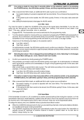
... your selection by briefly pressing the POWER button. 5. Values 9 and 0 are using your microphone, you are invalid. 4. In this case, start anew with step 2. 7. Disengage MUTE. 3.2.7 Turning the microphone off To turn the microphone off . Briefly press the POWER button. 3. If the setting for 2 seconds. ULTRALINK UL2000M For the Auto Mute function to work, it has to be activated on...
... your selection by briefly pressing the POWER button. 5. Values 9 and 0 are using your microphone, you are invalid. 4. In this case, start anew with step 2. 7. Disengage MUTE. 3.2.7 Turning the microphone off To turn the microphone off . Briefly press the POWER button. 3. If the setting for 2 seconds. ULTRALINK UL2000M For the Auto Mute function to work, it has to be activated on...
Manual
Page 17
... by brief pauses. Adjusting the angle at all . ULTRALINK UL2000M If the receiver is not powered on, no status is set to OFF). 2. The position of medium-tempo blinks. 3.3.4 Mic Gain 1. Briefly press the POWER button. 3. Just like during programming, 6 blink medium-tempo codes indicate the individual digits that the microphone is not set to 1, 2, 3 or 4 and confirm your selection by...
... by brief pauses. Adjusting the angle at all . ULTRALINK UL2000M If the receiver is not powered on, no status is set to OFF). 2. The position of medium-tempo blinks. 3.3.4 Mic Gain 1. Briefly press the POWER button. 3. Just like during programming, 6 blink medium-tempo codes indicate the individual digits that the microphone is not set to 1, 2, 3 or 4 and confirm your selection by...
Manual
Page 19
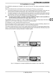
...one rack bracket on top of power amplifiers or other unit. If you wish to install only one unit in a rack, mount a rack bracket to one of the sides. To install 2 receivers in a rack, first connect the two receivers to one another , causing ...multiple ULR2000s when installed on top of the receiver into the rack. 2. For installation in a rack. INSTALLATION 19 ULTRALINK UL2000M 5.2 Installation in a rack The ULR2000's antennae are additional 10 cm (4 inches) of free space in the back for connecting cables. This allows unproblematic installation in a rack, use M6 machine ...
...one rack bracket on top of power amplifiers or other unit. If you wish to install only one unit in a rack, mount a rack bracket to one of the sides. To install 2 receivers in a rack, first connect the two receivers to one another , causing ...multiple ULR2000s when installed on top of the receiver into the rack. 2. For installation in a rack. INSTALLATION 19 ULTRALINK UL2000M 5.2 Installation in a rack The ULR2000's antennae are additional 10 cm (4 inches) of free space in the back for connecting cables. This allows unproblematic installation in a rack, use M6 machine ...
Manual
Page 20
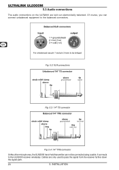
Of course, you can not be connected using a cable. Cables are laid out electronically balanced. INSTALLATION It connects to the balanced connectors. ULTRALINK UL2000M 5.3 Audio connections The audio connections on the ULR2000 are only used to pass the signal from the receiver farther down the signal path. 20 5. Fig. 5.2: XLR connections Fig. 5.3: 1/4" TS connector Fig. 5.4: 1/4" TRS connector Unlike other microphones, the ULM2000 hand-held transmitter can connect unbalanced equipment to the ULR2000 receiver wirelessly.
Of course, you can not be connected using a cable. Cables are laid out electronically balanced. INSTALLATION It connects to the balanced connectors. ULTRALINK UL2000M 5.3 Audio connections The audio connections on the ULR2000 are only used to pass the signal from the receiver farther down the signal path. 20 5. Fig. 5.2: XLR connections Fig. 5.3: 1/4" TS connector Fig. 5.4: 1/4" TRS connector Unlike other microphones, the ULM2000 hand-held transmitter can connect unbalanced equipment to the ULR2000 receiver wirelessly.
Manual
Page 22
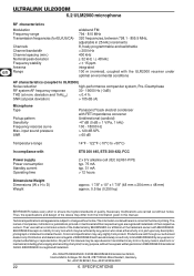
...), coupled with the ULR2000 receiver under optimal environmental conditions AF characteristics (coupled to change without notice. Thus, the specifications and design of any kind, for any description, photograph or statement contained herein. The names of their respective owners. BEHRINGER is correct at peak deviation) < 0.4 % > 105 dB (A) Microphone Type Pickup pattern Sensitivity Frequency resonse curve Max. Products are...
...), coupled with the ULR2000 receiver under optimal environmental conditions AF characteristics (coupled to change without notice. Thus, the specifications and design of any kind, for any description, photograph or statement contained herein. The names of their respective owners. BEHRINGER is correct at peak deviation) < 0.4 % > 105 dB (A) Microphone Type Pickup pattern Sensitivity Frequency resonse curve Max. Products are...

Manual
Page 23
... off and on, the user is encouraged to try to correct the interference by MUSIC Group can radiate radio frequency energy and, if not installed and used in accordance with the instructions, may cause undesired operation. FEDERAL COMMUNICATIONS COMMISSION COMPLIANCE INFORMATION ULTRALINK ULM2000/ULR2000 Responsible party name: Address: Phone/Fax No.: MUSIC Group Services USA, Inc. 18912 North...
... off and on, the user is encouraged to try to correct the interference by MUSIC Group can radiate radio frequency energy and, if not installed and used in accordance with the instructions, may cause undesired operation. FEDERAL COMMUNICATIONS COMMISSION COMPLIANCE INFORMATION ULTRALINK ULM2000/ULR2000 Responsible party name: Address: Phone/Fax No.: MUSIC Group Services USA, Inc. 18912 North...


