Quick Start Guide
Page 1
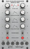
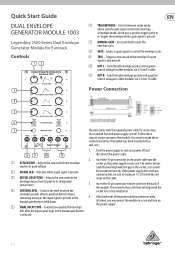
... a case and turn on the cable. 3. After both ends of the envelope if a gate signal is present. (3) INITIAL DECAY TIME - Connect a gate signal to start the envelope cycle. (8) GATE- It is released. Insert the 10-pin connector into the socket on the power supply or rack case. V 1.0 Quick Start Guide DUAL ENVELOPE GENERATOR MODULE 1003 Legendary 2500 Series Dual Envelope Generator Module for connecting to a standard Eurorack power supply system. Send the left envelope positive and negative control voltage to other modules via 3.5 mm...
... a case and turn on the cable. 3. After both ends of the envelope if a gate signal is present. (3) INITIAL DECAY TIME - Connect a gate signal to start the envelope cycle. (8) GATE- It is released. Insert the 10-pin connector into the socket on the power supply or rack case. V 1.0 Quick Start Guide DUAL ENVELOPE GENERATOR MODULE 1003 Legendary 2500 Series Dual Envelope Generator Module for connecting to a standard Eurorack power supply system. Send the left envelope positive and negative control voltage to other modules via 3.5 mm...
Quick Start Guide
Page 2
... Max input level Outputs Out A Type Impedance Max output level Out B Type Impedance Max output level 3.5 mm TS jack, DC coupled >35 kΩ +4 V +12 V 3.5 mm TS jack, DC coupled >20 kΩ +4 V +12 V 2 x 3.5 mm TS jacks, DC coupled 1 kΩ -10 V or +10 V 2 x 3.5 mm TS jacks, DC coupled 1 kΩ -10 V or +10 V Controls Attack Initial decay Sustain Final decay Trigger modes Manual gate Power Power supply Current draw Physical Dimensions Rack...
... Max input level Outputs Out A Type Impedance Max output level Out B Type Impedance Max output level 3.5 mm TS jack, DC coupled >35 kΩ +4 V +12 V 3.5 mm TS jack, DC coupled >20 kΩ +4 V +12 V 2 x 3.5 mm TS jacks, DC coupled 1 kΩ -10 V or +10 V 2 x 3.5 mm TS jacks, DC coupled 1 kΩ -10 V or +10 V Controls Attack Initial decay Sustain Final decay Trigger modes Manual gate Power Power supply Current draw Physical Dimensions Rack...


