Specifications Sheet
Page 2
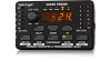
DSP110 SHARK® Easy-to-use automatic FEEDBACK DESTROYER with additional learn function for reliable feedback suppression s Variable delay line with up to 2.5 seconds of delay, adjustable ... vice versa s Status LED's for all 12 filters s Two 24-bit A/D and D/A converters s Servo-balanced inputs and outputs with XLR and 1/4" phone connectors s Rugged external power supply for maximum signal integrity and headroom s 6-segment clip level meter with clipping indicator s 4-digit multi-function display s 19" rack-mounting kit for...
DSP110 SHARK® Easy-to-use automatic FEEDBACK DESTROYER with additional learn function for reliable feedback suppression s Variable delay line with up to 2.5 seconds of delay, adjustable ... vice versa s Status LED's for all 12 filters s Two 24-bit A/D and D/A converters s Servo-balanced inputs and outputs with XLR and 1/4" phone connectors s Rugged external power supply for maximum signal integrity and headroom s 6-segment clip level meter with clipping indicator s 4-digit multi-function display s 19" rack-mounting kit for...
Manual
Page 2
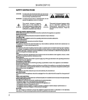
... the ventilation openings: or placed in a built-in installation, such as marked on the appliance and in the accompanying literature. The power supply cord or the plug has been damaged; No user serviceable parts inside the enclosure - This symbol, wherever it appears, alerts you... Heed Warnings: All warnings on the appliance. Grounding or Polarization: Precautions should not be walked on or pinched by the manufacturer. SHARK DSP110 SAFETY INSTRUCTIONS CAUTION: To reduce the risk of electrical shock, do not expose this appliance to rain or moisture. This symbol, wherever...
... the ventilation openings: or placed in a built-in installation, such as marked on the appliance and in the accompanying literature. The power supply cord or the plug has been damaged; No user serviceable parts inside the enclosure - This symbol, wherever it appears, alerts you... Heed Warnings: All warnings on the appliance. Grounding or Polarization: Precautions should not be walked on or pinched by the manufacturer. SHARK DSP110 SAFETY INSTRUCTIONS CAUTION: To reduce the risk of electrical shock, do not expose this appliance to rain or moisture. This symbol, wherever...
Manual
Page 5
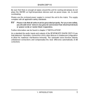
to the mains. As a standard the audio inputs and outputs of the BEHRINGER SHARK DSP110 are fully balanced. Please use the enclosed power supply to connect the unit to avoid overheating. The automatic servo function detects unbalanced connections and compensates the level difference automatically (6 dB correction). 1. For your own ...
to the mains. As a standard the audio inputs and outputs of the BEHRINGER SHARK DSP110 are fully balanced. Please use the enclosed power supply to connect the unit to avoid overheating. The automatic servo function detects unbalanced connections and compensates the level difference automatically (6 dB correction). 1. For your own ...
Manual
Page 10
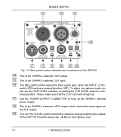
...not light up. 17 Use the POWER SUPPLY CONNECTOR to midtravel position. Possible values are: +4 dBu or microphone level. 10 1. INTRODUCTION To adjust microphone levels you can use the CLIP LEVEL indicator, by the outputs of the DSP110 14 This is the SHARK’s balanced XLR output. 15 ...the CLIP LEVEL control to hook up the SHARK’s external power supply. 18 This is the SHARK’s balanced XLR input. 16 The MIC GAIN control adjust the input signal gain, when the INPUT LEVEL switch has been pressed (position: MIC). SHARK DSP110 Fig 1.3: Rear panel control elements and ...
...not light up. 17 Use the POWER SUPPLY CONNECTOR to midtravel position. Possible values are: +4 dBu or microphone level. 10 1. INTRODUCTION To adjust microphone levels you can use the CLIP LEVEL indicator, by the outputs of the DSP110 14 This is the SHARK’s balanced XLR output. 15 ...the CLIP LEVEL control to hook up the SHARK’s external power supply. 18 This is the SHARK’s balanced XLR input. 16 The MIC GAIN control adjust the input signal gain, when the INPUT LEVEL switch has been pressed (position: MIC). SHARK DSP110 Fig 1.3: Rear panel control elements and ...
Manual
Page 11
...feedback. APPLICATIONS 2.1 Wiring the DSP110: general remarks With its great versatility the SHARK can activate the SHARK’s Low Cut filter. APPLICATIONS 11 We therefore recommend that the CLIP-LED will not light up. 22 The PHANTOM switch enables the Phantom Power supply required for a variety of... the most common applications. 2.1.1 Connection between your mixing console (OUTPUT LEVEL switch set the SHARK’s OUTPUT switch to +4 dBu (switch pressed) and adapt the ...
...feedback. APPLICATIONS 2.1 Wiring the DSP110: general remarks With its great versatility the SHARK can activate the SHARK’s Low Cut filter. APPLICATIONS 11 We therefore recommend that the CLIP-LED will not light up. 22 The PHANTOM switch enables the Phantom Power supply required for a variety of... the most common applications. 2.1.1 Connection between your mixing console (OUTPUT LEVEL switch set the SHARK’s OUTPUT switch to +4 dBu (switch pressed) and adapt the ...

Manual
Page 22
...Nominal Operating Level Max. Output Level SYSTEM SPECIFICATIONS Frequency Response Noise THD DIGITAL PROCESSING Converters Sampling Rate DISPLAY Type POWER SUPPLY Mains Voltages PHYSICAL Dimensions (H * W * D) Net Weight XLR and 1/4" jack RF filtered, servo-balanced... ~, 50 - 60 Hz approx. 2 1/4" (56 mm) x 3 1/2" (88 mm) x 5 1/8" (130 mm) approx. 0.5 kg BEHRINGER is constantly striving to existing products without prior notice. Specifications and appearance may be made from those listed or illustrated. 22 4. SPECIFICATIONS As a result of... Operating Level Max. SHARK DSP110 4.
...Nominal Operating Level Max. Output Level SYSTEM SPECIFICATIONS Frequency Response Noise THD DIGITAL PROCESSING Converters Sampling Rate DISPLAY Type POWER SUPPLY Mains Voltages PHYSICAL Dimensions (H * W * D) Net Weight XLR and 1/4" jack RF filtered, servo-balanced... ~, 50 - 60 Hz approx. 2 1/4" (56 mm) x 3 1/2" (88 mm) x 5 1/8" (130 mm) approx. 0.5 kg BEHRINGER is constantly striving to existing products without prior notice. Specifications and appearance may be made from those listed or illustrated. 22 4. SPECIFICATIONS As a result of... Operating Level Max. SHARK DSP110 4.

Manual
Page 23
..., please disconnect the Power Supply Units from the SHARKs! After you have fixed all screws solidly. 5. You need two screws to position the single SHARKs on two units of the rackmount (see fig. 5.1). RACKMOUNT (OPTIONAL) 23 Just take a cross-point screwdriver and tighten both screws loosely. Now you can fix the DSP110 onto the rackmount...
..., please disconnect the Power Supply Units from the SHARKs! After you have fixed all screws solidly. 5. You need two screws to position the single SHARKs on two units of the rackmount (see fig. 5.1). RACKMOUNT (OPTIONAL) 23 Just take a cross-point screwdriver and tighten both screws loosely. Now you can fix the DSP110 onto the rackmount...


