Specifications Sheet
Page 2
... adjustable cut-off frequency s Ultra-low noise microphone pre amp with 60 dB gain control and +48 V phantom power s Level conversion from line to microphone level and vice versa s Status LED's for all 12 filters s Two 24-bit A/D and D/A converters s Servo-balanced inputs and outputs with XLR and 1/4" phone connectors s Rugged external power supply for maximum signal integrity and headroom s 6-segment clip level meter with clipping indicator s 4-digit multi-function display...
... adjustable cut-off frequency s Ultra-low noise microphone pre amp with 60 dB gain control and +48 V phantom power s Level conversion from line to microphone level and vice versa s Status LED's for all 12 filters s Two 24-bit A/D and D/A converters s Servo-balanced inputs and outputs with XLR and 1/4" phone connectors s Rugged external power supply for maximum signal integrity and headroom s 6-segment clip level meter with clipping indicator s 4-digit multi-function display...
Specifications Sheet
Page 3
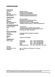
Input Level AUDIO OUTPUTS Connectors Type Impedance Nominal Operating Level Max. As a result of these efforts, modifications may differ from time to time to maintain the highest professional standards. Output Level SYSTEM SPECIFICATIONS Frequency Response Noise THD DIGITAL PROCESSING Converters Sampling Rate DISPLAY Type POWER SUPPLY Mains Voltages PHYSICAL Dimensions (H * W * D) Net Weight XLR and 1/4" phone RF filtered, servo-balanced input 6 kΩ balanced, 3 kΩ unbalanced microphone or line level source (switchable) +19 dBu at...
Input Level AUDIO OUTPUTS Connectors Type Impedance Nominal Operating Level Max. As a result of these efforts, modifications may differ from time to time to maintain the highest professional standards. Output Level SYSTEM SPECIFICATIONS Frequency Response Noise THD DIGITAL PROCESSING Converters Sampling Rate DISPLAY Type POWER SUPPLY Mains Voltages PHYSICAL Dimensions (H * W * D) Net Weight XLR and 1/4" phone RF filtered, servo-balanced input 6 kΩ balanced, 3 kΩ unbalanced microphone or line level source (switchable) +19 dBu at...
Manual
Page 2
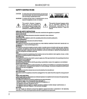
... from the appliance. Power-Cord Protection: Power supply cords should be followed. Damage Requiring Service: The appliance should be adhered to cords and plugs, convenience receptacles and the point where they are not spilled into the appliance; or - refer servicing to operate normally or exhibits a marked change in a wet basement, or near water (e.g. Read the manual. Follow instructions: All operation and user instructions should not be...
... from the appliance. Power-Cord Protection: Power supply cords should be followed. Damage Requiring Service: The appliance should be adhered to cords and plugs, convenience receptacles and the point where they are not spilled into the appliance; or - refer servicing to operate normally or exhibits a marked change in a wet basement, or near water (e.g. Read the manual. Follow instructions: All operation and user instructions should not be...
Manual
Page 3
... with graphic equalizers, or to assign this task to suppress feedback with a multitude of speaker cabinets have quite an impact on the sound image. However, the individual filters of our FEEDBACK DESTROYER PRO DSP1124P, a variable Delay Line (adjustable in msec, feet and meter), a ULN (Ultra-Low Noise) microphone pre-amp with their relatively wide bandwidth, have led to a multi-channel system using the ingenious...
... with graphic equalizers, or to assign this task to suppress feedback with a multitude of speaker cabinets have quite an impact on the sound image. However, the individual filters of our FEEDBACK DESTROYER PRO DSP1124P, a variable Delay Line (adjustable in msec, feet and meter), a ULN (Ultra-Low Noise) microphone pre-amp with their relatively wide bandwidth, have led to a multi-channel system using the ingenious...
Manual
Page 5
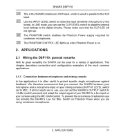
... not place the SHARK on high-temperature devices such as power amps, etc. As a standard the audio inputs and outputs of the BEHRINGER SHARK DSP110 are fully balanced. to the mains. The automatic servo function detects unbalanced connections and compensates the level difference automatically (6 dB correction). 1. Please use the enclosed power supply to connect the unit to avoid overheating. Further information can be grounded...
... not place the SHARK on high-temperature devices such as power amps, etc. As a standard the audio inputs and outputs of the BEHRINGER SHARK DSP110 are fully balanced. to the mains. The automatic servo function detects unbalanced connections and compensates the level difference automatically (6 dB correction). 1. Please use the enclosed power supply to connect the unit to avoid overheating. Further information can be grounded...
Manual
Page 6
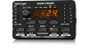
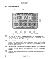
... CLIP LEVEL control does not affect the input/output levels, but adapts the audio signal as optimally as possible to the threshold of the digital circuitry. Any corrections can be adjusted on the display . 6 1. Be sure that can be made with the CLIP LEVEL control . SHARK DSP110 1.3 Control elements Fig. 1.2: Front panel control elements of the DSP110 1 2 + 3 The CLIP LEVEL METER shows you can shift the operating level upwards/downwards...
... CLIP LEVEL control does not affect the input/output levels, but adapts the audio signal as optimally as possible to the threshold of the digital circuitry. Any corrections can be adjusted on the display . 6 1. Be sure that can be made with the CLIP LEVEL control . SHARK DSP110 1.3 Control elements Fig. 1.2: Front panel control elements of the DSP110 1 2 + 3 The CLIP LEVEL METER shows you can shift the operating level upwards/downwards...
Manual
Page 7
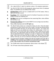
... 4-digit display reads the last figure only when you use extremely small steps when editing parameters. The control LED lights up the selection, briefly press the key located next to adjust the Delay Line time. This function can use the DELAY function. The selection speed will be used for all filters are currently in the display . 8 The UP button raises these parameter values. 1. Press the button several times to...
... 4-digit display reads the last figure only when you use extremely small steps when editing parameters. The control LED lights up the selection, briefly press the key located next to adjust the Delay Line time. This function can use the DELAY function. The selection speed will be used for all filters are currently in the display . 8 The UP button raises these parameter values. 1. Press the button several times to...
Manual
Page 8
... through 100 (full sensitivity). Pressing the LOW CUT button for feedback frequencies and assigns free filters to adjust the DENSITY parameter, which controls the Compressor’s attack and release times from 0 (no sensitivity) through -44 dB). Pressing the GATE button for a longer time (please wait, until all five parameter LEDs light up) enables the GATE LEARN function, which automatically searches for a longer...
... through 100 (full sensitivity). Pressing the LOW CUT button for feedback frequencies and assigns free filters to adjust the DENSITY parameter, which controls the Compressor’s attack and release times from 0 (no sensitivity) through -44 dB). Pressing the GATE button for a longer time (please wait, until all five parameter LEDs light up) enables the GATE LEARN function, which automatically searches for a longer...
Manual
Page 9
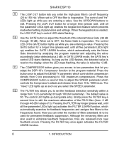
... free filters are output with a level of a RESET. set inoperative filters to the DSP110’s input, where feedbacks are inoperative which have not yet found a feedback frequency. After a short delay, the unit returns to the FILTER menu. + The FILTER LEARN function generates short feedback-causing signals that the FILTER LEARN function works properly, the short feedback-causing signals are needed to -30 dB below digital maximum. Fixed...
... free filters are output with a level of a RESET. set inoperative filters to the DSP110’s input, where feedbacks are inoperative which have not yet found a feedback frequency. After a short delay, the unit returns to the FILTER menu. + The FILTER LEARN function generates short feedback-causing signals that the FILTER LEARN function works properly, the short feedback-causing signals are needed to -30 dB below digital maximum. Fixed...
Manual
Page 10
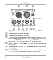
... not light up. 17 Use the POWER SUPPLY CONNECTOR to hook up the SHARK’s external power supply. 18 This is the SHARK’s balanced XLR input. 16 The MIC GAIN control adjust the input signal gain, when the INPUT LEVEL switch has been pressed (position: MIC). INTRODUCTION To adjust microphone levels you can use the CLIP LEVEL indicator, by the outputs of the DSP110 14 This is the SHARK’s balanced XLR output. 15...
... not light up. 17 Use the POWER SUPPLY CONNECTOR to hook up the SHARK’s external power supply. 18 This is the SHARK’s balanced XLR input. 16 The MIC GAIN control adjust the input signal gain, when the INPUT LEVEL switch has been pressed (position: MIC). INTRODUCTION To adjust microphone levels you can use the CLIP LEVEL indicator, by the outputs of the DSP110 14 This is the SHARK’s balanced XLR output. 15...
Manual
Page 11
...;s OUTPUT switch to +4 dBu (switch pressed) and adapt the output signal of subsonics you are using the MIC GAIN control. Please make sure that you connect the SHARK between microphone and mixing console In live applications it is wired in use the CLIP LEVEL control to adapt the internal level settings to the digital circuitry. SHARK DSP110 20 This is the SHARK’s balanced JACK input, which is often useful to protect specific single microphones...
...;s OUTPUT switch to +4 dBu (switch pressed) and adapt the output signal of subsonics you are using the MIC GAIN control. Please make sure that you connect the SHARK between microphone and mixing console In live applications it is wired in use the CLIP LEVEL control to adapt the internal level settings to the digital circuitry. SHARK DSP110 20 This is the SHARK’s balanced JACK input, which is often useful to protect specific single microphones...
Manual
Page 13
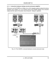
APPLICATIONS 13 Fig. 2.3: The SHARK connected between the console’s output and the input of the power amp driving the “delayed” speakers. SHARK DSP110 2.1.3 Connection between mixing console and power amplifier When you use the SHARK as a Delay Line unit for speaker systems placed at various positions (see chapter 2.3), you should connect the SHARK between console and power amp 2.
APPLICATIONS 13 Fig. 2.3: The SHARK connected between the console’s output and the input of the power amp driving the “delayed” speakers. SHARK DSP110 2.1.3 Connection between mixing console and power amplifier When you use the SHARK as a Delay Line unit for speaker systems placed at various positions (see chapter 2.3), you should connect the SHARK between console and power amp 2.
Manual
Page 16
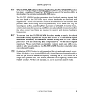
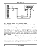
... louder in ” your sound reinforcement system: once the system has been installed and set up, open all microphone channels and monitor paths, then enable FILTER LEARN mode on your DSP110. APPLICATIONS But with the DSP110 you could raise the overall volume level only until the first feedback occurs. If you are using not just one DSP110 for the monitor path, you should employ...
... louder in ” your sound reinforcement system: once the system has been installed and set up, open all microphone channels and monitor paths, then enable FILTER LEARN mode on your DSP110. APPLICATIONS But with the DSP110 you could raise the overall volume level only until the first feedback occurs. If you are using not just one DSP110 for the monitor path, you should employ...

Manual
Page 17
... you power up the SHARK). those used on how to efficiently remove the feedback. In FILTER LEARN mode, feedback is enlarged whenever the feedback frequency shifts slightly. The filter width is generated and suppressed automatically. Much like signal portions produced by guitars or keyboards. The standard setting is ideally suitable for a more quickly. the frequency remains fixed but...
... you power up the SHARK). those used on how to efficiently remove the feedback. In FILTER LEARN mode, feedback is enlarged whenever the feedback frequency shifts slightly. The filter width is generated and suppressed automatically. Much like signal portions produced by guitars or keyboards. The standard setting is ideally suitable for a more quickly. the frequency remains fixed but...
Manual
Page 18
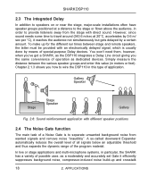
... times between the various speaker groups and enter this type of operation as a moderately and accurately set Gate it reaches the audience not simultaneously but gets delayed by means of special-purpose Delay devices. Simply measure the distance between stage and remote speakers, the latter must be provided with direct sound. Fig. 2.6: Sound reinforcement application with different speaker positions 2.4 The Noise Gate function...
... times between the various speaker groups and enter this type of operation as a moderately and accurately set Gate it reaches the audience not simultaneously but gets delayed by means of special-purpose Delay devices. Simply measure the distance between stage and remote speakers, the latter must be provided with direct sound. Fig. 2.6: Sound reinforcement application with different speaker positions 2.4 The Noise Gate function...
Manual
Page 19
... out low-frequency signal portions such as the microphone is not in this function before the concert and after the sound check. crosstalk of that features a very high slope. When you adjust the Gate threshold. If the adjusted value yields unsatisfactory results, the UP/DOWN buttons can be suppressed or acoustically “contaminated” recordings can also damage power amps and...
... out low-frequency signal portions such as the microphone is not in this function before the concert and after the sound check. crosstalk of that features a very high slope. When you adjust the Gate threshold. If the adjusted value yields unsatisfactory results, the UP/DOWN buttons can be suppressed or acoustically “contaminated” recordings can also damage power amps and...
Manual
Page 20
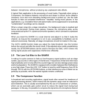
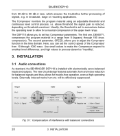
...trouble-free operation, even at high operating levels. compression). Output Pin 1 Pin 2 = (+) Signal Pin 3 = (-) Signal Cable 2 1 3 Shield (+) Signal + Hum (-) Signal + Hum RFI and Hum Input Ground 1 2 Positive 3 Negative (+)Hum + Signal (-)Hum + Signal 2 x Signal = Signal + 6 dB Fig. 3.1: Compensation of the upper level range. Use small values to make the Compressor respond to smallest level differences, and high values to adjust the Compressor function in the time domain. INSTALLATION 3.1 Audio connections As standard, the BEHRINGER DSP110 is installed with balanced...
...trouble-free operation, even at high operating levels. compression). Output Pin 1 Pin 2 = (+) Signal Pin 3 = (-) Signal Cable 2 1 3 Shield (+) Signal + Hum (-) Signal + Hum RFI and Hum Input Ground 1 2 Positive 3 Negative (+)Hum + Signal (-)Hum + Signal 2 x Signal = Signal + 6 dB Fig. 3.1: Compensation of the upper level range. Use small values to make the Compressor respond to smallest level differences, and high values to adjust the Compressor function in the time domain. INSTALLATION 3.1 Audio connections As standard, the BEHRINGER DSP110 is installed with balanced...

Manual
Page 22
SPECIFICATIONS AUDIO INPUTS Connectors Type Impedance Nominal Operating Level Max. Specifications and appearance may be made from those listed or illustrated. 22 4. SHARK DSP110 4. Output Level SYSTEM SPECIFICATIONS Frequency Response Noise THD DIGITAL PROCESSING Converters Sampling Rate DISPLAY Type POWER SUPPLY Mains Voltages PHYSICAL Dimensions (H * W * D) Net Weight XLR and 1/4" jack RF filtered, servo-balanced input 6 kOhms balanced, 3 kOhms unbalanced microphone or line level source (switchable) +19 dBu at microphone level and line level XLR and 1/4" jack electronically...
SPECIFICATIONS AUDIO INPUTS Connectors Type Impedance Nominal Operating Level Max. Specifications and appearance may be made from those listed or illustrated. 22 4. SHARK DSP110 4. Output Level SYSTEM SPECIFICATIONS Frequency Response Noise THD DIGITAL PROCESSING Converters Sampling Rate DISPLAY Type POWER SUPPLY Mains Voltages PHYSICAL Dimensions (H * W * D) Net Weight XLR and 1/4" jack RF filtered, servo-balanced input 6 kOhms balanced, 3 kOhms unbalanced microphone or line level source (switchable) +19 dBu at microphone level and line level XLR and 1/4" jack electronically...
Manual
Page 25
...use the online registration option via the Internet (www.behringer.com or www.behringer.de). § 2 WARRANTY 4. with the warranty regulations described below. Any product deemed eligible for freight and packing. No part of this manual may also choose to give any such modification/adaptation, irrespective of the problem. WARRANTY 25 Free inspections and maintenance/repair work...to submit a written repair order within the specified warranty period that does not comply with the return authorization number to return the card in BEHRINGER user or service manuals. 1. If the ...
...use the online registration option via the Internet (www.behringer.com or www.behringer.de). § 2 WARRANTY 4. with the warranty regulations described below. Any product deemed eligible for freight and packing. No part of this manual may also choose to give any such modification/adaptation, irrespective of the problem. WARRANTY 25 Free inspections and maintenance/repair work...to submit a written repair order within the specified warranty period that does not comply with the return authorization number to return the card in BEHRINGER user or service manuals. 1. If the ...
Manual
Page 26
... the receiving antenna. • Increase the separation between the equipment and receiver. • Connect the equipment into an outlet on a circuit different from that to which can be determined by turning the equipment off and on, the user is encouraged to try to correct the interference by MUSIC Group can radiate radio frequency energy and, if not installed and used in...
... the receiving antenna. • Increase the separation between the equipment and receiver. • Connect the equipment into an outlet on a circuit different from that to which can be determined by turning the equipment off and on, the user is encouraged to try to correct the interference by MUSIC Group can radiate radio frequency energy and, if not installed and used in...


