Quick Start Guide
Page 1
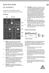
... via cables with 3.5 mm TS connectors. 3. Insert the 10-pin connector into the module via stripe on the power supply. (5) V-TRIG OUT - Power Connection (6) (8) (1) AUDIO IN - When any valid V-TRIG input activates the S-TRIG output, any other V-TRIG input activity will align with the converted A signal for Eurorack Controls (1) (2) (4) (3) (5) (7) (6) V-TRIG IN A/B - The connector has a tab that will be inserted incorrectly. Quick Start Guide 961 INTERFACE Legendary Analog Multi-channel...
... via cables with 3.5 mm TS connectors. 3. Insert the 10-pin connector into the module via stripe on the power supply. (5) V-TRIG OUT - Power Connection (6) (8) (1) AUDIO IN - When any valid V-TRIG input activates the S-TRIG output, any other V-TRIG input activity will align with the converted A signal for Eurorack Controls (1) (2) (4) (3) (5) (7) (6) V-TRIG IN A/B - The connector has a tab that will be inserted incorrectly. Quick Start Guide 961 INTERFACE Legendary Analog Multi-channel...
Quick Start Guide
Page 2
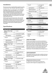
...) 1 x 3.5 mm jack, DC coupled Pull low to trigger +12 V 2 x 3.5 mm parallel jacks, DC coupled < 2 kΩ, unbalanced +5 V 2 x circuit (left and right) 6 x 3.5 mm jacks, DC coupled 10 kΩ, unbalanced +5 V + 1.5 V V-trig in B Input Impedance Maximum input level Minimum level to trigger S-trig out Operation Output level Controls Sensitivity Switch-on the rack case, there may be positioned in the approximate relation to start, which may be a series of fixed...
...) 1 x 3.5 mm jack, DC coupled Pull low to trigger +12 V 2 x 3.5 mm parallel jacks, DC coupled < 2 kΩ, unbalanced +5 V 2 x circuit (left and right) 6 x 3.5 mm jacks, DC coupled 10 kΩ, unbalanced +5 V + 1.5 V V-trig in B Input Impedance Maximum input level Minimum level to trigger S-trig out Operation Output level Controls Sensitivity Switch-on the rack case, there may be positioned in the approximate relation to start, which may be a series of fixed...


