User Guide
Page 4
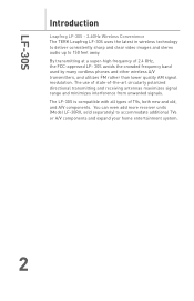
... crowded frequency band used by many cordless phones and other wireless A/V transmitters, and utilizes FM rather than lower quality AM signal modulation. By transmitting at a super-high frequency of ...and A/V components. LF-30S Introduction Leapfrog LF-30S - 2.4GHz Wireless Convenience The TERK Leapfrog LF-30S uses the latest in wireless technology to deliver consistently sharp and clear.... 2 The use of state-of-the-art circularly polarized directional transmitting and receiving antennas maximizes signal range and minimizes interference from unwanted signals. You can even add more ...
... crowded frequency band used by many cordless phones and other wireless A/V transmitters, and utilizes FM rather than lower quality AM signal modulation. By transmitting at a super-high frequency of ...and A/V components. LF-30S Introduction Leapfrog LF-30S - 2.4GHz Wireless Convenience The TERK Leapfrog LF-30S uses the latest in wireless technology to deliver consistently sharp and clear.... 2 The use of state-of-the-art circularly polarized directional transmitting and receiving antennas maximizes signal range and minimizes interference from unwanted signals. You can even add more ...

User Guide
Page 7
... that is connected to watch the A/V source video on the front of a TV set to the same channel for connection to the antenna and mechanical stopper will occur. D - 15V DC Power Port (both units - IR Extender Jack (transmitter only) Allows you wish to... the transmitter. G - Channel 3/4 Video Selector Switch (receiver only - Directional 2.4GHz antenna (both units) Sends and receives remote control signals. A - C - H - Antenna (both units) Sends and receives A/V signals. On/Off Switch (both units) Right and left stereo audio (red/...
... that is connected to watch the A/V source video on the front of a TV set to the same channel for connection to the antenna and mechanical stopper will occur. D - 15V DC Power Port (both units - IR Extender Jack (transmitter only) Allows you wish to... the transmitter. G - Channel 3/4 Video Selector Switch (receiver only - Directional 2.4GHz antenna (both units) Sends and receives remote control signals. A - C - H - Antenna (both units) Sends and receives A/V signals. On/Off Switch (both units) Right and left stereo audio (red/...
User Guide
Page 10
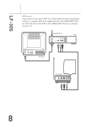
Cable/Antenna CABLE/ANT. IN VIDEO IN AUDIO IN LEFT RIGHT Television Transmitter RIGHT LEFT - + IR EXTENDER VIDEO IN AUDIO IN DC 15v 8 LF-30S VCR users: If you want to view your VCR on a TV located near the transmitter, connect a coaxial cable (not supplied) from the CABLE/ANT OUT (or OUT TO TV) on the VCR to the CABLE/ANT IN port connector on your TV. OUT VIDEO LINE OUT AUDIO LEFT RIGHT VCR CABLE/ ANT. IN CABLE/ANT.
Cable/Antenna CABLE/ANT. IN VIDEO IN AUDIO IN LEFT RIGHT Television Transmitter RIGHT LEFT - + IR EXTENDER VIDEO IN AUDIO IN DC 15v 8 LF-30S VCR users: If you want to view your VCR on a TV located near the transmitter, connect a coaxial cable (not supplied) from the CABLE/ANT OUT (or OUT TO TV) on the VCR to the CABLE/ANT IN port connector on your TV. OUT VIDEO LINE OUT AUDIO LEFT RIGHT VCR CABLE/ ANT. IN CABLE/ANT.
User Guide
Page 11
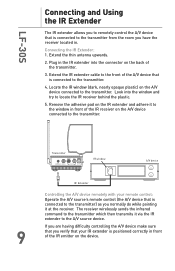
... located in the IR extender into the window and try to locate the IR receiver behind the plastic. 5. Connecting the IR Extender: 1. Extend the thin antenna upwards. 2. LF-30S Connecting and Using the IR Extender The IR extender allows you to remotely control the A/V device that is connected to the transmitter...
... located in the IR extender into the window and try to locate the IR receiver behind the plastic. 5. Connecting the IR Extender: 1. Extend the thin antenna upwards. 2. LF-30S Connecting and Using the IR Extender The IR extender allows you to remotely control the A/V device that is connected to the transmitter...

User Guide
Page 13
...), connect the white plugs on the cable to that single audio input and to the receiver's AUDIO LEFT jack. Note: If you already have an antenna or cable connected to your A/V source, you can also view any image sent by the transmitter (such as a sleeping baby monitored by your TV does...
...), connect the white plugs on the cable to that single audio input and to the receiver's AUDIO LEFT jack. Note: If you already have an antenna or cable connected to your A/V source, you can also view any image sent by the transmitter (such as a sleeping baby monitored by your TV does...

User Guide
Page 16
...For best performance, the units should face each other For maximum range between the transmitter and receiver units, try to force the antennas to pivot, they have limited rotation in either clockwise or counter-clockwise directions. Always make sure the receiver and transmitter units are directional... and Receiver Units The LF-30S system broadcasts video and audio using the square directional antennas and your TV, other electronics, large furniture or appliances. Do not try to fully rotate the antennas. Both the LF- 30S Transmitter and Receiver should be placed as high as your ...
...For best performance, the units should face each other For maximum range between the transmitter and receiver units, try to force the antennas to pivot, they have limited rotation in either clockwise or counter-clockwise directions. Always make sure the receiver and transmitter units are directional... and Receiver Units The LF-30S system broadcasts video and audio using the square directional antennas and your TV, other electronics, large furniture or appliances. Do not try to fully rotate the antennas. Both the LF- 30S Transmitter and Receiver should be placed as high as your ...

User Guide
Page 17
... transmitter are all components (DVD, VCR, TV etc.) in use connected to the same channel. Interference: Noisy picture or sound Adjust the receiver and transmitter's antenna orientation. Change the channels that the transmitter and receiver are firmly inserted into the units and into a power source. Move a microwave from an electrical outlet...
... transmitter are all components (DVD, VCR, TV etc.) in use connected to the same channel. Interference: Noisy picture or sound Adjust the receiver and transmitter's antenna orientation. Change the channels that the transmitter and receiver are firmly inserted into the units and into a power source. Move a microwave from an electrical outlet...
User Guide
Page 19
...encouraged to try to correct the interference by one or more of the following measures: • Re-orient or relocate the receiving antenna. • Increase the separation between the equipment and the receiver. • Connect the equipment into an outlet on a circuit ...accordance with the instructions, may cause undesired operation of the device. 17 Operation is connected. • Consult the dealer or an experienced radio/TV technician for a Class B digital device, pursuant to provide reasonable protection against harmful interference in a particular installation. Canada - This...
...encouraged to try to correct the interference by one or more of the following measures: • Re-orient or relocate the receiving antenna. • Increase the separation between the equipment and the receiver. • Connect the equipment into an outlet on a circuit ...accordance with the instructions, may cause undesired operation of the device. 17 Operation is connected. • Consult the dealer or an experienced radio/TV technician for a Class B digital device, pursuant to provide reasonable protection against harmful interference in a particular installation. Canada - This...


