

User Guide
Page 1
Z97-E Motherboard
Z97-E Motherboard

User Guide
Page 3
Contents Safety information...vi About this guide...vii Z97-E specifications summary ix Package contents...xiii Installation tools and components xiv Chapter 1: Product Introduction 1.1 Special features 1-1 1.1.1 Product highlights 1-1 1.1.2 5X Protection 1-2 1.1.3 ASUS Exclusive Features 1-2 1.2 Motherboard overview 1-3 1.2.1 Before you proceed 1-3 1.2.2 Motherboard layout 1-4 1.2.3 Central Processing Unit (CPU 1-6 1.2.4 System memory 1-7 1.2.5 Expansion slots 1-9 1.2.6 Jumpers 1-11 1.2.7 Onboard LEDs 1-12 1.2.8 Internal...
Contents Safety information...vi About this guide...vii Z97-E specifications summary ix Package contents...xiii Installation tools and components xiv Chapter 1: Product Introduction 1.1 Special features 1-1 1.1.1 Product highlights 1-1 1.1.2 5X Protection 1-2 1.1.3 ASUS Exclusive Features 1-2 1.2 Motherboard overview 1-3 1.2.1 Before you proceed 1-3 1.2.2 Motherboard layout 1-4 1.2.3 Central Processing Unit (CPU 1-6 1.2.4 System memory 1-7 1.2.5 Expansion slots 1-9 1.2.6 Jumpers 1-11 1.2.7 Onboard LEDs 1-12 1.2.8 Internal...
User Guide
Page 9
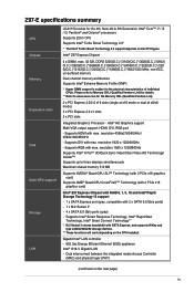
Please refer to Memory QVL (Qualified Vendors List) for details. ** Refer to www.asus.com for the 4th, New 4th & 5th Generation Intel® Core™ i7 / i5 / i3, Pentium® and Celeron® processors Supports 22nm ...with SATA Express, and supports M Key and type 2242/2260/2280 storage devices. ** These functions will work depending on the next page) ix Intel® Z97 Express Chipset 4 x DIMM, max. 32 GB, DDR3 3200(O.C.)*/3100(O.C.)*/3000(O.C.)*/2933( O.C.)*/2800(O.C.)*/2666(O.C.)*/2600(O.C.)*/2400(O.C.)*/2250(O.C.)*/220 0(O.C.)*/2133(O.C.)*/2000(O.C.)*/1866(O.C.)*/1600/1333 MHz, ...
Please refer to Memory QVL (Qualified Vendors List) for details. ** Refer to www.asus.com for the 4th, New 4th & 5th Generation Intel® Core™ i7 / i5 / i3, Pentium® and Celeron® processors Supports 22nm ...with SATA Express, and supports M Key and type 2242/2260/2280 storage devices. ** These functions will work depending on the next page) ix Intel® Z97 Express Chipset 4 x DIMM, max. 32 GB, DDR3 3200(O.C.)*/3100(O.C.)*/3000(O.C.)*/2933( O.C.)*/2800(O.C.)*/2666(O.C.)*/2600(O.C.)*/2400(O.C.)*/2250(O.C.)*/220 0(O.C.)*/2133(O.C.)*/2000(O.C.)*/1866(O.C.)*/1600/1333 MHz, ...

User Guide
Page 10
... at mid-board, 2 ports at back panel) Realtek® ALC892 7.1-channel high definition audio CODEC: - Short circuit damage prevention - ASUS High-Quality 5K-Hour Solid Capacitors - 2.5x long lifespan with fast response time M.2 & SATA Express onboard - Most advanced options with...ASUS Fan Xpert3 - LED-lit audio shielding: Ensures precision analog/digital separation and greatly reduced multi-lateral interference, with the most fun gaming platform under Windows® system (continued on the next page) x Z97-E specifications summary USB Audio ASUS Exclusive Features Intel® Z97...
... at mid-board, 2 ports at back panel) Realtek® ALC892 7.1-channel high definition audio CODEC: - Short circuit damage prevention - ASUS High-Quality 5K-Hour Solid Capacitors - 2.5x long lifespan with fast response time M.2 & SATA Express onboard - Most advanced options with...ASUS Fan Xpert3 - LED-lit audio shielding: Ensures precision analog/digital separation and greatly reduced multi-lateral interference, with the most fun gaming platform under Windows® system (continued on the next page) x Z97-E specifications summary USB Audio ASUS Exclusive Features Intel® Z97...
User Guide
Page 11
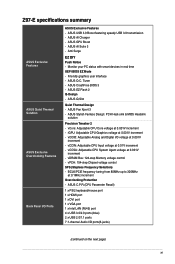
... Core voltage at 0.1MHz increment Overclocking Protection - ASUS USB 3.0 Boost featuring speedy USB 3.0 transmission - ASUS CrashFree BIOS 3 - vDRAM Bus: 124-step Memory voltage control - ASUS EZ Flash 2 Q-Design - ASUS Stylish Fanless Design: PCH Heat-sink & MOS Heatsink solution Precision Tweaker 2 - Z97-E specifications summary ASUS Exclusive Features ASUS Quiet Thermal Solution ASUS Exclusive Overclocking Features Back Panel I /O ports(6-jacks...
... Core voltage at 0.1MHz increment Overclocking Protection - ASUS USB 3.0 Boost featuring speedy USB 3.0 transmission - ASUS CrashFree BIOS 3 - vDRAM Bus: 124-step Memory voltage control - ASUS EZ Flash 2 Q-Design - ASUS Stylish Fanless Design: PCH Heat-sink & MOS Heatsink solution Precision Tweaker 2 - Z97-E specifications summary ASUS Exclusive Features ASUS Quiet Thermal Solution ASUS Exclusive Overclocking Features Back Panel I /O ports(6-jacks...
User Guide
Page 12
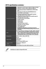
Z97-E specifications summary Internal I/O Connectors BIOS Manageability Support DVD Operating system support Form factor 1 x USB 3.0/2.0 connectors support additional 2 USB ports (19-pin) 3 x USB 2.0/1/1 connectors support additional 6 ... fan installed and switches to the control mode automatically. 64 Mb Flash ROM, UEFI AMI BIOS, PnP, DMI2.7, WfM2.0, SM BIOS 2.8, ACPI 5.0, Multi-language BIOS, ASUS EZ Flash 2, CrashFree BIOS 3, F6 Qfan Control, F11 EZ Tuning Wizard, F3 My Favorites & Shortcut, Quick Note, Last Modified log, F12 PrintScreen, and...
Z97-E specifications summary Internal I/O Connectors BIOS Manageability Support DVD Operating system support Form factor 1 x USB 3.0/2.0 connectors support additional 2 USB ports (19-pin) 3 x USB 2.0/1/1 connectors support additional 6 ... fan installed and switches to the control mode automatically. 64 Mb Flash ROM, UEFI AMI BIOS, PnP, DMI2.7, WfM2.0, SM BIOS 2.8, ACPI 5.0, Multi-language BIOS, ASUS EZ Flash 2, CrashFree BIOS 3, F6 Qfan Control, F11 EZ Tuning Wizard, F3 My Favorites & Shortcut, Quick Note, Last Modified log, F12 PrintScreen, and...
User Guide
Page 13
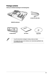
xiii Actual product specifications may vary with different models. Package contents Check your motherboard package for the following items ASUS Z97-E motherboard 2 x Serial ATA 6 Gb/s cables 1 x ASUS I/O Shield User Manual User manual Support DVD • If any of the above items is damaged or missing, contact your retailer. • The illustrated items above are for reference only.
xiii Actual product specifications may vary with different models. Package contents Check your motherboard package for the following items ASUS Z97-E motherboard 2 x Serial ATA 6 Gb/s cables 1 x ASUS I/O Shield User Manual User manual Support DVD • If any of the above items is damaged or missing, contact your retailer. • The illustrated items above are for reference only.

User Guide
Page 15
...It also features backward compatibility with its complete backward compatibility to two SATA drives of PCIe 2.0. Intel® Z97 Express Chipset Intel® Z97 Express Chipset is the PCI Express bus standard that provides twice the performance and speed of the same speed.... experienced before. It utilizes the serial point-to receive the freshest updates from a deep sleep or hibernate mode. Chapter 1 ASUS Z97-E 1-1 Chapter 1: Product Introduction Product introduction 1.1 Special features 1 1.1.1 Product highlights LGA1150 socket for Intel® integrated graphics performance...
...It also features backward compatibility with its complete backward compatibility to two SATA drives of PCIe 2.0. Intel® Z97 Express Chipset Intel® Z97 Express Chipset is the PCI Express bus standard that provides twice the performance and speed of the same speed.... experienced before. It utilizes the serial point-to receive the freshest updates from a deep sleep or hibernate mode. Chapter 1 ASUS Z97-E 1-1 Chapter 1: Product Introduction Product introduction 1.1 Special features 1 1.1.1 Product highlights LGA1150 socket for Intel® integrated graphics performance...
User Guide
Page 17
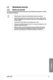
... the power supply case, to avoid damaging them due to static electricity. • Hold components by the edges to the motherboard, peripherals, or components. Chapter 1 ASUS Z97-E 1-3 Failure to do so may cause severe damage to avoid touching the ICs on them. • Whenever you uninstall any component, place it on a grounded...
... the power supply case, to avoid damaging them due to static electricity. • Hold components by the edges to the motherboard, peripherals, or components. Chapter 1 ASUS Z97-E 1-3 Failure to do so may cause severe damage to avoid touching the ICs on them. • Whenever you uninstall any component, place it on a grounded...
User Guide
Page 18
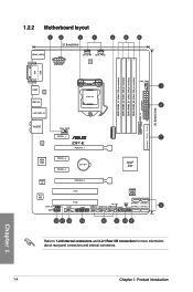
... USB3_56 LAN_USB3_34 LGA1150 CHA_FAN3 1 2 2 30.5cm(12.0in) USB3_12 EATXPWR SATAEXPRESS SATA6G_6 SATA6G_5 AUDIO Intel® I218-V ASM 1083 CHA_FAN1 PCIEX1_1 Z97-E PCIEX16_1 PCIEX1_2 PCIEX1_3 BATTERY M.2(SOCKET3) 7 Intel® Z97 Super I/O ALC 892 SPDIF_OUT AAFP PCIEX16_2 PCI1 64Mb BIOS PCI2 COM TPM SB_PWR CLRTC USB910 USB1112 USB1314 PANEL SATA6G_1 SATA6G_3 SATA6G_2 SATA6G_4...
... USB3_56 LAN_USB3_34 LGA1150 CHA_FAN3 1 2 2 30.5cm(12.0in) USB3_12 EATXPWR SATAEXPRESS SATA6G_6 SATA6G_5 AUDIO Intel® I218-V ASM 1083 CHA_FAN1 PCIEX1_1 Z97-E PCIEX16_1 PCIEX1_2 PCIEX1_3 BATTERY M.2(SOCKET3) 7 Intel® Z97 Super I/O ALC 892 SPDIF_OUT AAFP PCIEX16_2 PCI1 64Mb BIOS PCI2 COM TPM SB_PWR CLRTC USB910 USB1112 USB1314 PANEL SATA6G_1 SATA6G_3 SATA6G_2 SATA6G_4...
User Guide
Page 20
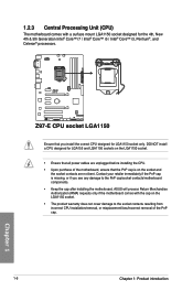
... Intel® Core™ i7 / Intel® Core™ i5 / Intel® Core™ i3, Pentium®, and Celeron® processors. ASUS will process Return Merchandise Authorization (RMA) requests only if the motherboard comes with a surface mount LGA1150 socket designed for LGA155 and LGA1156 sockets on the... LGA1150 socket. • Ensure that all power cables are not bent. Chapter 1 1-6 Chapter 1: Product introduction Z97-E Z97-E CPU socket LGA1150 Ensure that the PnP cap is missing, or if you install the correct CPU designed for LGA1150 socket only.
... Intel® Core™ i7 / Intel® Core™ i5 / Intel® Core™ i3, Pentium®, and Celeron® processors. ASUS will process Return Merchandise Authorization (RMA) requests only if the motherboard comes with a surface mount LGA1150 socket designed for LGA155 and LGA1156 sockets on the... LGA1150 socket. • Ensure that all power cables are not bent. Chapter 1 1-6 Chapter 1: Product introduction Z97-E Z97-E CPU socket LGA1150 Ensure that the PnP cap is missing, or if you install the correct CPU designed for LGA1150 socket only.
User Guide
Page 21
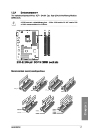
Z97-E Z97-E 240-pin DDR3 DIMM sockets Recommended memory configurations Chapter 1 ASUS Z97-E 1-7 A DDR3 module is notched differently from a DDR or DDR2 module. DIMM_A1 DIMM_A2 DIMM_B1 DIMM_B2 1.2.4 System memory The motherboard comes with four DDR 3 (Double Data Rate 3) Dual Inline Memory Modules (DIMM) slots. DO NOT install a DDR or DDR2 memory module to the DDR3 slot.
Z97-E Z97-E 240-pin DDR3 DIMM sockets Recommended memory configurations Chapter 1 ASUS Z97-E 1-7 A DDR3 module is notched differently from a DDR or DDR2 module. DIMM_A1 DIMM_A2 DIMM_B1 DIMM_B2 1.2.4 System memory The motherboard comes with four DDR 3 (Double Data Rate 3) Dual Inline Memory Modules (DIMM) slots. DO NOT install a DDR or DDR2 memory module to the DDR3 slot.
User Guide
Page 23
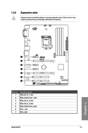
Failure to do so may cause you physical injury and damage motherboard components. 1.2.5 Expansion slots Unplug the power cord before adding or removing expansion cards. PCIEX1_1 Z97-E PCIEX16_1 PCIEX1_2 PCIEX1_3 PCIEX16_2 PCI1 PCI2 Slot No. 1 2 3 4 5 6 7 Slot Description PCIe 2.0 x1_1 slot PCIe 3.0/2.0 x16_1 slot PCIe 2.0 x1_2 slot PCIe 2.0 x1_3 slot PCIe 3.0/2.0 x16_2 slot PCI_1 slot PCI_2 slot ASUS Z97-E 1-9 Chapter 1
Failure to do so may cause you physical injury and damage motherboard components. 1.2.5 Expansion slots Unplug the power cord before adding or removing expansion cards. PCIEX1_1 Z97-E PCIEX16_1 PCIEX1_2 PCIEX1_3 PCIEX16_2 PCI1 PCI2 Slot No. 1 2 3 4 5 6 7 Slot Description PCIe 2.0 x1_1 slot PCIe 3.0/2.0 x16_1 slot PCIe 2.0 x1_2 slot PCIe 2.0 x1_3 slot PCIe 3.0/2.0 x16_2 slot PCI_1 slot PCI_2 slot ASUS Z97-E 1-9 Chapter 1
User Guide
Page 25
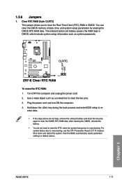
... setup parameters by erasing the CMOS RTC RAM data. Shut down the key during the boot process and enter BIOS setup to default values. Chapter 1 ASUS Z97-E 1-11 Hold down and reboot the system, then the BIOS automatically resets parameter settings to re- The onboard button cell battery powers the RAM data... to clear the Real Time Clock (RTC) RAM in CMOS, which include system setup information such as a screwdriver to clear the CMOS RTC RAM data. Z97-E CLRTC +3V_BAT GND PIN 1 Z97-E Clear RTC RAM To erase the RTC RAM: 1.
... setup parameters by erasing the CMOS RTC RAM data. Shut down the key during the boot process and enter BIOS setup to default values. Chapter 1 ASUS Z97-E 1-11 Hold down and reboot the system, then the BIOS automatically resets parameter settings to re- The onboard button cell battery powers the RAM data... to clear the Real Time Clock (RTC) RAM in CMOS, which include system setup information such as a screwdriver to clear the CMOS RTC RAM data. Z97-E CLRTC +3V_BAT GND PIN 1 Z97-E Clear RTC RAM To erase the RTC RAM: 1.

User Guide
Page 26
... up to indicate that you should shut down the system and unplug the power cable before removing or plugging in soft-off mode. Z97-E SB_PWR ON OFF Standby Power Powered Off Z97-E Standby power LED 1.2.8 Internal connectors 1. LPCPD# GND +3VSB NC LAD0 +3V LAD3 PCIRST# LFRAME# LCLK... Z97-E PIN 1 TPM NC CLKRUN# SERIRQ NC GND LAD1 LAD2 NC GND Z97-E TPM connector The TPM module is ON, in sleep mode, or in any motherboard component. TPM connector (20-1 pin TPM) This connector supports a...
... up to indicate that you should shut down the system and unplug the power cable before removing or plugging in soft-off mode. Z97-E SB_PWR ON OFF Standby Power Powered Off Z97-E Standby power LED 1.2.8 Internal connectors 1. LPCPD# GND +3VSB NC LAD0 +3V LAD3 PCIRST# LFRAME# LCLK... Z97-E PIN 1 TPM NC CLKRUN# SERIRQ NC GND LAD1 LAD2 NC GND Z97-E TPM connector The TPM module is ON, in sleep mode, or in any motherboard component. TPM connector (20-1 pin TPM) This connector supports a...
User Guide
Page 27
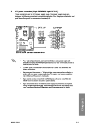
... are uncertain about the minimum power supply requirement for your system, refer to the Recommended Power Supply Wattage Calculator at http://support.asus. ATX power connectors (24-pin EATXPWR; 8-pin EATX12V) These connectors are for details. com/PowerSupplyCalculator/PSCalculator.aspx?SLanguage=en-us .... • If you want to use a power supply unit (PSU) that you are designed to connect the 4-pin/8-pin EATX12 V power plug. Chapter 1 ASUS Z97-E 1-13 EATX12V EATXPWR +12V DC +12V DC +12V DC +12V DC +3 Volts GND +12 Volts +5 Volts +12 Volts +5 Volts +5V Standby +5...
... are uncertain about the minimum power supply requirement for your system, refer to the Recommended Power Supply Wattage Calculator at http://support.asus. ATX power connectors (24-pin EATXPWR; 8-pin EATX12V) These connectors are for details. com/PowerSupplyCalculator/PSCalculator.aspx?SLanguage=en-us .... • If you want to use a power supply unit (PSU) that you are designed to connect the 4-pin/8-pin EATX12 V power plug. Chapter 1 ASUS Z97-E 1-13 EATX12V EATXPWR +12V DC +12V DC +12V DC +12V DC +3 Volts GND +12 Volts +5 Volts +12 Volts +5 Volts +5V Standby +5...
User Guide
Page 28
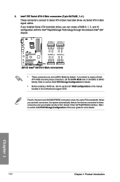
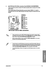
...motherboard support DVD. When you can create a RAID 0, 1, 5, and 10 configuration with the Intel® Rapid Storage Technology through the onboard Intel® Z97 chipset. Refer to [RAID Mode]. The M.2 Socket 3 and SATAEXPRESS connectors share the same PCIe bandwidth. GND RSATA_TXP1 RSATA_TXN1 GND RSATA_RXN1 RSATA_RXP1 GND GND RSATA_TXP3... set to Serial ATA 6 Gb/s hard disk drives via Serial ATA 6 Gb/s signal cables. Chapter 1 1-14 Chapter 1: Product introduction Intel® Z97 Serial ATA 6 Gb/s connectors (7-pin SATA6G_1~4 ) These connectors connect to [AHCI Mode] by default.
...motherboard support DVD. When you can create a RAID 0, 1, 5, and 10 configuration with the Intel® Rapid Storage Technology through the onboard Intel® Z97 chipset. Refer to [RAID Mode]. The M.2 Socket 3 and SATAEXPRESS connectors share the same PCIe bandwidth. GND RSATA_TXP1 RSATA_TXN1 GND RSATA_RXN1 RSATA_RXP1 GND GND RSATA_TXP3... set to Serial ATA 6 Gb/s hard disk drives via Serial ATA 6 Gb/s signal cables. Chapter 1 1-14 Chapter 1: Product introduction Intel® Z97 Serial ATA 6 Gb/s connectors (7-pin SATA6G_1~4 ) These connectors connect to [AHCI Mode] by default.
User Guide
Page 29
.... If you installed Serial ATA hard disk drives, you can support one SATA Express device or two SATA devices. Chapter 1 ASUS Z97-E 1-15 When you intend to create a Serial ATA RAID set using these connectors and set a higher priority to these connectors, set ...cables. 4. If you use both connectors, the system automatically detects the devices connected to M.2 Socket 3 than SATA Express slot. SATA6G_5 SATA6G_6 Z97-E GND RSATA_TXP5 RSATA_TXN5 GND RSATA_RXP5 RSATA_RXN5 GND GND RSATA_TXP6 RSATA_TXN6 GND RSATA_RXP6 RSATA_RXN6 GND Floating Device_Reset GND Detection SATAEXPRESS...
.... If you installed Serial ATA hard disk drives, you can support one SATA Express device or two SATA devices. Chapter 1 ASUS Z97-E 1-15 When you intend to create a Serial ATA RAID set using these connectors and set a higher priority to these connectors, set ...cables. 4. If you use both connectors, the system automatically detects the devices connected to M.2 Socket 3 than SATA Express slot. SATA6G_5 SATA6G_6 Z97-E GND RSATA_TXP5 RSATA_TXN5 GND RSATA_RXP5 RSATA_RXN5 GND GND RSATA_TXP6 RSATA_TXN6 GND RSATA_RXP6 RSATA_RXN6 GND Floating Device_Reset GND Detection SATAEXPRESS...

User Guide
Page 30
...Line out_R NC Line out_L PORT1 L PORT1 R PORT2 R SENSE_SEND PORT2 L HD-audio-compliant Legacy AC'97 pin definition compliant definition Z97-E Front panel audio connector • We recommend that supports either HD Audio or legacy AC`97 audio standard. Connect the S/PDIF ...capability. • If you connect a high-definition front panel audio module to this connector to avail of the system chassis. +5V SPDIFOUT GND Z97-E PIN 1 SPDIF_OUT Z97-E Digital audio connector The S/PDIF module is purchased separately. 6. Connect one end of the front panel audio I /O module that you want ...
...Line out_R NC Line out_L PORT1 L PORT1 R PORT2 R SENSE_SEND PORT2 L HD-audio-compliant Legacy AC'97 pin definition compliant definition Z97-E Front panel audio connector • We recommend that supports either HD Audio or legacy AC`97 audio standard. Connect the S/PDIF ...capability. • If you connect a high-definition front panel audio module to this connector to avail of the system chassis. +5V SPDIFOUT GND Z97-E PIN 1 SPDIF_OUT Z97-E Digital audio connector The S/PDIF module is purchased separately. 6. Connect one end of the front panel audio I /O module that you want ...
User Guide
Page 31
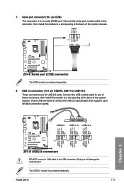
...Connect the USB module cable to any of these connectors, then install the module to a slot opening at the back of the system chassis. ASUS Z97-E 1-17 Connect the serial port module cable to this connector, then install the module to a slot opening at the back of the system ... 1 PIN 1 PIN 1 USB+5V USB_P10USB_P10+ GND USB+5V USB_P12USB_P12+ GND USB+5V USB_P14USB_P14+ GND Z97-E USB2.0 connectors DO NOT connect a 1394 cable to 48 Mb/s connection speed. COM PIN 1 Z97-E Z97-E Serial port (COM) connector The COM module is purchased separately. RXD DTR DSR CTS DCD TXD GND RTS RI...
...Connect the USB module cable to any of these connectors, then install the module to a slot opening at the back of the system chassis. ASUS Z97-E 1-17 Connect the serial port module cable to this connector, then install the module to a slot opening at the back of the system ... 1 PIN 1 PIN 1 USB+5V USB_P10USB_P10+ GND USB+5V USB_P12USB_P12+ GND USB+5V USB_P14USB_P14+ GND Z97-E USB2.0 connectors DO NOT connect a 1394 cable to 48 Mb/s connection speed. COM PIN 1 Z97-E Z97-E Serial port (COM) connector The COM module is purchased separately. RXD DTR DSR CTS DCD TXD GND RTS RI...
