User Manual
Page 4
Contents 2.5.7 Installing an ASUS PIKE RAID card 2-22 2.5.8 Installing i Button 2-23 2.5.9 Installing ASMB4 management board 2-23 2.5.10 Connect Thermal sensor cable 2-24 2.5.11 Installing the audio card 2-24 2.6 Jumpers 2-...3.2.1 Using the OS shut down function 3-4 3.2.2 Using the dual function power switch 3-4 Chapter 4: BIOS setup 4.1 Managing and updating your BIOS 4-3 4.1.1 AFUDOS utility 4-3 4.1.2 ASUS CrashFree BIOS 3 utility 4-6 4.2 BIOS setup program 4-7 4.2.1 BIOS menu screen 4-8 4.2.2 Menu bar 4-8 4.2.3 Navigation keys 4-8 4.2.4 Menu items 4-9 4.2.5 Sub-menu items 4-9...
Contents 2.5.7 Installing an ASUS PIKE RAID card 2-22 2.5.8 Installing i Button 2-23 2.5.9 Installing ASMB4 management board 2-23 2.5.10 Connect Thermal sensor cable 2-24 2.5.11 Installing the audio card 2-24 2.6 Jumpers 2-...3.2.1 Using the OS shut down function 3-4 3.2.2 Using the dual function power switch 3-4 Chapter 4: BIOS setup 4.1 Managing and updating your BIOS 4-3 4.1.1 AFUDOS utility 4-3 4.1.2 ASUS CrashFree BIOS 3 utility 4-6 4.2 BIOS setup program 4-7 4.2.1 BIOS menu screen 4-8 4.2.2 Menu bar 4-8 4.2.3 Navigation keys 4-8 4.2.4 Menu items 4-9 4.2.5 Sub-menu items 4-9...

User Manual
Page 43
... management card in place. ASUS Z8PE-D12 Series 2-23 Snap the I Button slot on the motherboard. 2. Locate the BMC_FW header on your motherboard. 1. 2.5.8 Installing i Button Follow the steps below to install an optional i Button on the motherboard. 2. You need to install I Button before using PIKE 1078 functions. 2.5.9 Installing ASMB4 management board Follow the steps below to...
... management card in place. ASUS Z8PE-D12 Series 2-23 Snap the I Button slot on the motherboard. 2. Locate the BMC_FW header on your motherboard. 1. 2.5.8 Installing i Button Follow the steps below to install an optional i Button on the motherboard. 2. You need to install I Button before using PIKE 1078 functions. 2.5.9 Installing ASMB4 management board Follow the steps below to...
User Manual
Page 58
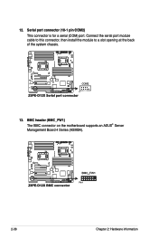
Connect the serial port module cable to this connector, then install the module to a slot opening at the back of the system chassis. 13. 12. BMC header (BMC_FW1) The BMC connector on the motherboard supports an ASUS® Server Management Board 4 Series (ASMB4). 2-38 Chapter 2: Hardware information Serial port connector (10-1 pin COM2) This connector is for a serial (COM) port.
Connect the serial port module cable to this connector, then install the module to a slot opening at the back of the system chassis. 13. 12. BMC header (BMC_FW1) The BMC connector on the motherboard supports an ASUS® Server Management Board 4 Series (ASMB4). 2-38 Chapter 2: Hardware information Serial port connector (10-1 pin COM2) This connector is for a serial (COM) port.


