User Manual
Page 4
Contents 2.5.7 Installing an ASUS PIKE RAID card 2-22 2.5.8 Installing i Button 2-23 2.5.9 Installing ASMB4 management board 2-23 2.5.10 Connect Thermal sensor cable 2-24 2.5.11 Installing the audio card 2-24 2.6 Jumpers 2-...3.2.1 Using the OS shut down function 3-4 3.2.2 Using the dual function power switch 3-4 Chapter 4: BIOS setup 4.1 Managing and updating your BIOS 4-3 4.1.1 AFUDOS utility 4-3 4.1.2 ASUS CrashFree BIOS 3 utility 4-6 4.2 BIOS setup program 4-7 4.2.1 BIOS menu screen 4-8 4.2.2 Menu bar 4-8 4.2.3 Navigation keys 4-8 4.2.4 Menu items 4-9 4.2.5 Sub-menu items 4-9...
Contents 2.5.7 Installing an ASUS PIKE RAID card 2-22 2.5.8 Installing i Button 2-23 2.5.9 Installing ASMB4 management board 2-23 2.5.10 Connect Thermal sensor cable 2-24 2.5.11 Installing the audio card 2-24 2.6 Jumpers 2-...3.2.1 Using the OS shut down function 3-4 3.2.2 Using the dual function power switch 3-4 Chapter 4: BIOS setup 4.1 Managing and updating your BIOS 4-3 4.1.1 AFUDOS utility 4-3 4.1.2 ASUS CrashFree BIOS 3 utility 4-6 4.2 BIOS setup program 4-7 4.2.1 BIOS menu screen 4-8 4.2.2 Menu bar 4-8 4.2.3 Navigation keys 4-8 4.2.4 Menu items 4-9 4.2.5 Sub-menu items 4-9...

User Manual
Page 43
... I Button before using PIKE 1078 functions. You need to install an optional i Button on your motherboard. 1. Snap the I Button before using PIKE 1078 functions. 2.5.9 Installing ASMB4 management board Follow the steps below to install I Button in place. ASUS Z8PE-D12 Series 2-23 Orient and press the ASMB4 management card in place. You need to...
... I Button before using PIKE 1078 functions. You need to install an optional i Button on your motherboard. 1. Snap the I Button before using PIKE 1078 functions. 2.5.9 Installing ASMB4 management board Follow the steps below to install I Button in place. ASUS Z8PE-D12 Series 2-23 Orient and press the ASMB4 management card in place. You need to...
User Manual
Page 58
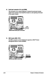
12. Serial port connector (10-1 pin COM2) This connector is for a serial (COM) port. Connect the serial port module cable to this connector, then install the module to a slot opening at the back of the system chassis. 13. BMC header (BMC_FW1) The BMC connector on the motherboard supports an ASUS® Server Management Board 4 Series (ASMB4). 2-38 Chapter 2: Hardware information
12. Serial port connector (10-1 pin COM2) This connector is for a serial (COM) port. Connect the serial port module cable to this connector, then install the module to a slot opening at the back of the system chassis. 13. BMC header (BMC_FW1) The BMC connector on the motherboard supports an ASUS® Server Management Board 4 Series (ASMB4). 2-38 Chapter 2: Hardware information


