User Guide
Page 13
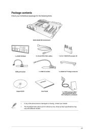
Actual product specifications may vary with different models. xiii Package contents Check your motherboard package for the following items ASUS X99-M WS motherboard 1 x ASUS Q-Shield 8 x Serial ATA 6 Gb/s cables 1 x 2-in-1 ASUS Q-Connector kit COM port bracket 1 x USB 2.0 module User Manual 1 x ASUS SLI™ bridge connector Support DVD User Guide 1 x 3T3R dual-band Wi-Fi moving antennas (Wi-Fi 802.11a/b/g/n/ac compliant) • If any of the above items is damaged or missing, contact your retailer. • The illustrated items above are for reference only.
Actual product specifications may vary with different models. xiii Package contents Check your motherboard package for the following items ASUS X99-M WS motherboard 1 x ASUS Q-Shield 8 x Serial ATA 6 Gb/s cables 1 x 2-in-1 ASUS Q-Connector kit COM port bracket 1 x USB 2.0 module User Manual 1 x ASUS SLI™ bridge connector Support DVD User Guide 1 x 3T3R dual-band Wi-Fi moving antennas (Wi-Fi 802.11a/b/g/n/ac compliant) • If any of the above items is damaged or missing, contact your retailer. • The illustrated items above are for reference only.
User Guide
Page 15
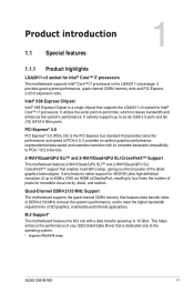
Chapter 1 ASUS X99-M WS 1-1 It also features native support for incredible visual clarity, detail, and realism. This helps enhance the performance of your SSD (Solid State Drive) that is a ... high definition) resolution of up to 4096 x 2160 via HDMI or DisplayPort, resulting to the operating system. * Supports PCIe/SATA mode. Intel® X99 Express Chipset Intel® X99 Express Chipset is dedicated only to four times the number of PCIe 2.0. PCI Express® 3.0 PCI Express® 3.0 (PCIe 3.0) is the PCI Express...
Chapter 1 ASUS X99-M WS 1-1 It also features native support for incredible visual clarity, detail, and realism. This helps enhance the performance of your SSD (Solid State Drive) that is a ... high definition) resolution of up to 4096 x 2160 via HDMI or DisplayPort, resulting to the operating system. * Supports PCIe/SATA mode. Intel® X99 Express Chipset Intel® X99 Express Chipset is dedicated only to four times the number of PCIe 2.0. PCI Express® 3.0 PCI Express® 3.0 (PCIe 3.0) is the PCI Express...
User Guide
Page 17
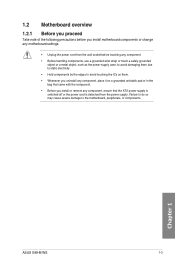
... you uninstall any component, place it on them due to static electricity. • Hold components by the edges to the motherboard, peripherals, or components. Chapter 1 ASUS X99-M WS 1-3 Failure to do so may cause severe damage to avoid touching the ICs on a grounded antistatic pad or in the bag that came with the...
... you uninstall any component, place it on them due to static electricity. • Hold components by the edges to the motherboard, peripherals, or components. Chapter 1 ASUS X99-M WS 1-3 Failure to do so may cause severe damage to avoid touching the ICs on a grounded antistatic pad or in the bag that came with the...
User Guide
Page 19
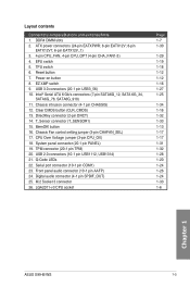
... 1-7 1-30 1-29 1-19 1-18 1-12 1-12 1-16 1-27 1-25 1-34 1-16 1-32 1-33 1-13 1-17 1-17 1-31 1-32 1-28 1-20 1-24 1-26 1-24 1-33 1-6 Chapter 1 ASUS X99-M WS 1-5 TPU switch 6. Clear CMOS button (CLR_CMOS) 13. button 16. Digital audio connector (4-1 pin SPDIF_OUT) 25. Intel® Serial ATA 6 Gb/s connectors (7-pin SATA6G_12, SATA 6G_34...
... 1-7 1-30 1-29 1-19 1-18 1-12 1-12 1-16 1-27 1-25 1-34 1-16 1-32 1-33 1-13 1-17 1-17 1-31 1-32 1-28 1-20 1-24 1-26 1-24 1-33 1-6 Chapter 1 ASUS X99-M WS 1-5 TPU switch 6. Clear CMOS button (CLR_CMOS) 13. button 16. Digital audio connector (4-1 pin SPDIF_OUT) 25. Intel® Serial ATA 6 Gb/s connectors (7-pin SATA6G_12, SATA 6G_34...
User Guide
Page 21
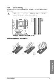
1.2.4 System memory The motherboard comes with four DDR 4 (Double Data Rate 4) Quad Inline Memory Modules (DIMM) slots. Recommended memory configurations Chapter 1 ASUS X99-M WS 1-7 DO NOT install a DDR, DDR2, or DDR3 memory module to the DDR4 slot. A DDR4 module is notched differently from a DDR, DDR2, or DDR3 module.
1.2.4 System memory The motherboard comes with four DDR 4 (Double Data Rate 4) Quad Inline Memory Modules (DIMM) slots. Recommended memory configurations Chapter 1 ASUS X99-M WS 1-7 DO NOT install a DDR, DDR2, or DDR3 memory module to the DDR4 slot. A DDR4 module is notched differently from a DDR, DDR2, or DDR3 module.
User Guide
Page 23
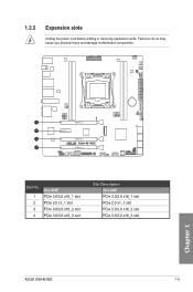
Chapter 1 Slot No. 1 2 3 4 40-LANE PCIe 3.0/2.0 x16_1 slot PCIe 2.0 x1_1 slot PCIe 3.0/2.0 x16_2 slot PCIe 3.0/2.0 x16_3 slot Slot Description 28-LANE PCIe 3.0/2.0 x16_1 slot PCIe 2.0 x1_1 slot PCIe 3.0/2.0 x16_2 slot PCIe 3.0/2.0 x16_3 slot ASUS X99-M WS 1-9 Failure to do so may cause you physical injury and damage motherboard components. 1.2.5 Expansion slots Unplug the power cord before adding or removing expansion cards.
Chapter 1 Slot No. 1 2 3 4 40-LANE PCIe 3.0/2.0 x16_1 slot PCIe 2.0 x1_1 slot PCIe 3.0/2.0 x16_2 slot PCIe 3.0/2.0 x16_3 slot Slot Description 28-LANE PCIe 3.0/2.0 x16_1 slot PCIe 2.0 x1_1 slot PCIe 3.0/2.0 x16_2 slot PCIe 3.0/2.0 x16_3 slot ASUS X99-M WS 1-9 Failure to do so may cause you physical injury and damage motherboard components. 1.2.5 Expansion slots Unplug the power cord before adding or removing expansion cards.
User Guide
Page 25
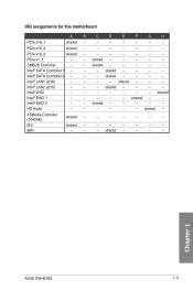
SMBUS Controller - - Intel® SATA Controller 2 - - - ASMedia Controller (1042AE) shared - - - - - - - Chapter 1 ASUS X99-M WS 1-11 PCIe x16_3 shared - - - - - - - shared - - - - HD Audio - - - - - - M.2 shared - - - - - - - shared - - - - - Intel® SATA Controller 1 - - - shared - - - - - - shared - - - - - PCIe x1_1 - - shared - - - - - IRQ assignments for this motherboard A B C D E F G H PCIe x16_1 ...
SMBUS Controller - - Intel® SATA Controller 2 - - - ASMedia Controller (1042AE) shared - - - - - - - Chapter 1 ASUS X99-M WS 1-11 PCIe x16_3 shared - - - - - - - shared - - - - HD Audio - - - - - - M.2 shared - - - - - - - shared - - - - - Intel® SATA Controller 1 - - - shared - - - - - - shared - - - - - PCIe x1_1 - - shared - - - - - IRQ assignments for this motherboard A B C D E F G H PCIe x16_1 ...
User Guide
Page 27
... in the Memory QVL (Qualified Vendors Lists) in this user manual or at www.asus.com. • If you that the BIOS has been restored to the latest BIOS version from www.asus.com after using the MemOK! ASUS X99-M WS 1-13 Chapter 1 button does not function under Windows® OS environment. • During the...
... in the Memory QVL (Qualified Vendors Lists) in this user manual or at www.asus.com. • If you that the BIOS has been restored to the latest BIOS version from www.asus.com after using the MemOK! ASUS X99-M WS 1-13 Chapter 1 button does not function under Windows® OS environment. • During the...
User Guide
Page 29
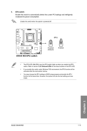
... the next system bootup. • You may change the EPU settings in BIOS setup program and enable the EPU function at the same time. Chapter 1 ASUS X99-M WS 1-15 EPU switch Enable this switch to section 1.2.8 Onboard LEDs for the exact location of the EPU LED. • If you enable this switch when...
... the next system bootup. • You may change the EPU settings in BIOS setup program and enable the EPU function at the same time. Chapter 1 ASUS X99-M WS 1-15 EPU switch Enable this switch to section 1.2.8 Onboard LEDs for the exact location of the EPU LED. • If you enable this switch when...
User Guide
Page 31
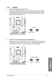
Chapter 1 ASUS X99-M WS 1-17 Set pins 2-3 to set a higher CPU voltage for the front fans and rear fans control. To go back to its default CPU voltage setting, ...
Chapter 1 ASUS X99-M WS 1-17 Set pins 2-3 to set a higher CPU voltage for the front fans and rear fans control. To go back to its default CPU voltage setting, ...
User Guide
Page 33
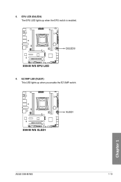
EPU LED (O2LED3) The EPU LED lights up when you enable the EZ XMP switch. 3. Chapter 1 ASUS X99-M WS 1-19 EZ XMP LED (XLED1) This LED lights up when the EPU switch is enabled. 4.
EPU LED (O2LED3) The EPU LED lights up when you enable the EZ XMP switch. 3. Chapter 1 ASUS X99-M WS 1-19 EZ XMP LED (XLED1) This LED lights up when the EPU switch is enabled. 4.
User Guide
Page 35
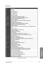
... Agent initialization is started Post-Memory PCH initialization is started DXE IPL is started Recovery firmware image is found (continued on the next page) Chapter 1 ASUS X99-M WS 1-21 Q-Code table Code 00 02 03 04 06 10 11 - 14 15 - 18 19 - 1C 2B - 2F 30 31 32 - 36 37 - 3A 3B...
... Agent initialization is started Post-Memory PCH initialization is started DXE IPL is started Recovery firmware image is found (continued on the next page) Chapter 1 ASUS X99-M WS 1-21 Q-Code table Code 00 02 03 04 06 10 11 - 14 15 - 18 19 - 1C 2B - 2F 30 31 32 - 36 37 - 3A 3B...
User Guide
Page 37
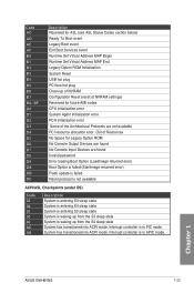
... Option ROM Initialization System Reset USB hot plug PCI bus hot plug Clean-up from the S3 sleep state System is in PIC mode. Chapter 1 ASUS X99-M WS 1-23
... Option ROM Initialization System Reset USB hot plug PCI bus hot plug Clean-up from the S3 sleep state System is in PIC mode. Chapter 1 ASUS X99-M WS 1-23
User Guide
Page 39
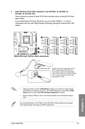
... to [RAID Mode]. 3. If you can create a RAID 0, 1, 5, and 10 configuration with the Intel® Rapid Storage Technology through the onboard Intel® X99 chipset. ASUS X99-M WS 1-25 Intel® X99 Serial ATA 6 Gb/s connectors (7-pin SATA6G_12, SATA6G_34, SATA6G_78, SATA6G_910) These connectors connect to chipset behavior, the SATA6G_78 and SATA6G_910 ports (black) do not...
... to [RAID Mode]. 3. If you can create a RAID 0, 1, 5, and 10 configuration with the Intel® Rapid Storage Technology through the onboard Intel® X99 chipset. ASUS X99-M WS 1-25 Intel® X99 Serial ATA 6 Gb/s connectors (7-pin SATA6G_12, SATA6G_34, SATA6G_78, SATA6G_910) These connectors connect to chipset behavior, the SATA6G_78 and SATA6G_910 ports (black) do not...
User Guide
Page 41
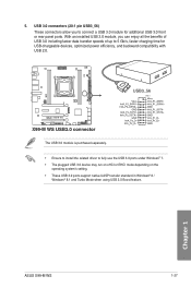
Chapter 1 ASUS X99-M WS 1-27 USB 3.0 connectors (20-1 pin USB3_56) These connectors allow you can enjoy all the benefits of USB 3.0 including faster data transfer speeds of up to 5 ...
Chapter 1 ASUS X99-M WS 1-27 USB 3.0 connectors (20-1 pin USB3_56) These connectors allow you can enjoy all the benefits of USB 3.0 including faster data transfer speeds of up to 5 ...
User Guide
Page 43
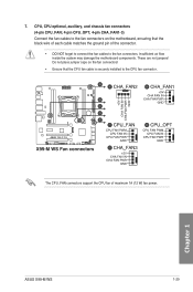
ASUS X99-M WS 1-29 Chapter 1 The CPU_FAN connectors support the CPU fan of the connector. • DO NOT forget to connect the fan cables to the CPU fan ...
ASUS X99-M WS 1-29 Chapter 1 The CPU_FAN connectors support the CPU fan of the connector. • DO NOT forget to connect the fan cables to the CPU fan ...
User Guide
Page 45
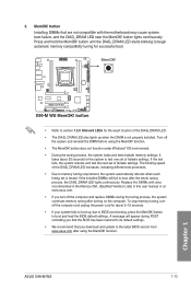
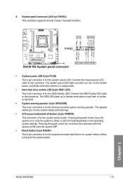
.... • ATX power button/soft-off the system power. The system power LED lights up or flashes when data is for the HDD Activity LED. ASUS X99-M WS 1-31 Chapter 1 9. Pressing the power button turns the system on the system power, and blinks when the system is for the system power button. Connect...
.... • ATX power button/soft-off the system power. The system power LED lights up or flashes when data is for the HDD Activity LED. ASUS X99-M WS 1-31 Chapter 1 9. Pressing the power button turns the system on the system power, and blinks when the system is for the system power button. Connect...
User Guide
Page 47
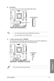
Chapter 1 The thermistor cable is for the thermistor cable that allows you to monitor the temperature of your motherboard's critical components and connected devices. ASUS X99-M WS 1-33 M.2 socket 3 This socket allows you to install an M.2 (NGFF) SSD module. • This socket supports M Key and type 2260/2280 storage devices. • This socket supports PCIe and SATA modes. 13. T_Sensor connector (2-pin T_SENSOR1) This connector is purchased separately. 12.
Chapter 1 The thermistor cable is for the thermistor cable that allows you to monitor the temperature of your motherboard's critical components and connected devices. ASUS X99-M WS 1-33 M.2 socket 3 This socket allows you to install an M.2 (NGFF) SSD module. • This socket supports M Key and type 2260/2280 storage devices. • This socket supports PCIe and SATA modes. 13. T_Sensor connector (2-pin T_SENSOR1) This connector is purchased separately. 12.
User Guide
Page 49
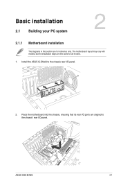
Place the motherboard into the chassis, ensuring that its rear I/O ports are for all models. 1. Basic installation 2.1 Building your PC system 2 2.1.1 Motherboard installation The diagrams in this section are aligned to the chassis rear I/O panel. 2. Install the ASUS Q-Shield to the chassis' rear I/O panel. Chapter 2 ASUS X99-M WS 2-1 The motherboard layout may vary with models, but the installation steps are the same for reference only.
Place the motherboard into the chassis, ensuring that its rear I/O ports are for all models. 1. Basic installation 2.1 Building your PC system 2 2.1.1 Motherboard installation The diagrams in this section are aligned to the chassis rear I/O panel. 2. Install the ASUS Q-Shield to the chassis' rear I/O panel. Chapter 2 ASUS X99-M WS 2-1 The motherboard layout may vary with models, but the installation steps are the same for reference only.
User Guide
Page 51
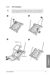
2.1.2 CPU installation Please note the order in place and the hatch properly sealed down. The plastic cap will pop up automatically once the CPU is in opening/ closing the double latch. C A B A B Triangle mark B A Triangle mark Chapter 2 ASUS X99-M WS 2-3 Follow the instructions printed on the metal sealing hatch or the illustrations shown below in this manual.
2.1.2 CPU installation Please note the order in place and the hatch properly sealed down. The plastic cap will pop up automatically once the CPU is in opening/ closing the double latch. C A B A B Triangle mark B A Triangle mark Chapter 2 ASUS X99-M WS 2-3 Follow the instructions printed on the metal sealing hatch or the illustrations shown below in this manual.


