
X99-DELUXE II user s manual English
Page 3
Contents Safety information...vi About this guide...vii X99-DELUXE II specifications summary ix Package contents...xvi Installation tools and components xviii Chapter 1: Product Introduction 1.1 ... Installation 2.1 Building your PC system 2-1 2.1.1 Motherboard installation 2-1 2.1.2 CPU installation 2-3 2.1.3 CPU heatsink and fan assembly installation 2-5 2.1.4 DIMM installation 2-6 2.1.5 ATX power connection 2-7 2.1.6 SATA device connection 2-8 2.1.7 Front I/O connector 2-9 2.1.8 Expansion card installation 2-10 2.1.9 Wi-Fi antenna installation 2-14 2.2 BIOS update ...
Contents Safety information...vi About this guide...vii X99-DELUXE II specifications summary ix Package contents...xvi Installation tools and components xviii Chapter 1: Product Introduction 1.1 ... Installation 2.1 Building your PC system 2-1 2.1.1 Motherboard installation 2-1 2.1.2 CPU installation 2-3 2.1.3 CPU heatsink and fan assembly installation 2-5 2.1.4 DIMM installation 2-6 2.1.5 ATX power connection 2-7 2.1.6 SATA device connection 2-8 2.1.7 Front I/O connector 2-9 2.1.8 Expansion card installation 2-10 2.1.9 Wi-Fi antenna installation 2-14 2.2 BIOS update ...
X99-DELUXE II user s manual English
Page 15
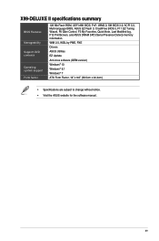
... Update Anti-virus software (OEM version) Windows® 10 Windows® 8.1 Windows® 7 ATX Form Factor, 12" x 9.6" (30.5cm x 24.4cm) • Specifications are subject to change without notice. • Visit the ASUS website for the software manual. X99-DELUXE II specifications summary BIOS Features Manageability Support DVD contents Operating system support Form factor 128...
... Update Anti-virus software (OEM version) Windows® 10 Windows® 8.1 Windows® 7 ATX Form Factor, 12" x 9.6" (30.5cm x 24.4cm) • Specifications are subject to change without notice. • Visit the ASUS website for the software manual. X99-DELUXE II specifications summary BIOS Features Manageability Support DVD contents Operating system support Form factor 128...

X99-DELUXE II user s manual English
Page 19
... as the power supply case, to avoid damaging them due to static electricity. • Hold components by the edges to the motherboard, peripherals, or components. ASUS X99-DELUXE II Series 1-1 Failure to do so may cause severe damage to avoid touching the ICs on them. • Whenever you uninstall any component, place it on... a grounded antistatic pad or in the bag that came with the component. • Before you install or remove any component, ensure that the ATX power supply is switched off or the power cord is detached from the power supply.
... as the power supply case, to avoid damaging them due to static electricity. • Hold components by the edges to the motherboard, peripherals, or components. ASUS X99-DELUXE II Series 1-1 Failure to do so may cause severe damage to avoid touching the ICs on them. • Whenever you uninstall any component, place it on... a grounded antistatic pad or in the bag that came with the component. • Before you install or remove any component, ensure that the ATX power supply is switched off or the power cord is detached from the power supply.

X99-DELUXE II user s manual English
Page 21
... 1-24 1-21 1-14 1-14 1-29 1-28 1-30 1-25 1-13 1-23 1-32 1-31 1-29 1-13 1-17 1-11 1-11 1-22 1-22 ASUS X99-DELUXE II Series 1-3 button 6. DirectKey connector (2-pin DRCT) 12. MemOK! Intel® Serial ATA 6 Gb/s connectors (7-pin SATA6G_12, SATA 6G_34, SATA 6G_56/SATAEXPRESS_1,...DIMM slots 2. Clear CMOS button (CLR_CMOS) 21. U.2 connector (U.2_1-2) 8. USB 3.0 connectors (20-1 pin USB3_12, USB3_34) 17. ATX power connectors (24-pin EATXPWR; 8-pin EATX12V_1; 4-pin EATX12V_2) 4. Chapter 1 Layout contents Connectors/Jumpers/Buttons and switches/Slots 1. Thunderbolt header (5-...
... 1-24 1-21 1-14 1-14 1-29 1-28 1-30 1-25 1-13 1-23 1-32 1-31 1-29 1-13 1-17 1-11 1-11 1-22 1-22 ASUS X99-DELUXE II Series 1-3 button 6. DirectKey connector (2-pin DRCT) 12. MemOK! Intel® Serial ATA 6 Gb/s connectors (7-pin SATA6G_12, SATA 6G_34, SATA 6G_56/SATAEXPRESS_1,...DIMM slots 2. Clear CMOS button (CLR_CMOS) 21. U.2 connector (U.2_1-2) 8. USB 3.0 connectors (20-1 pin USB3_12, USB3_34) 17. ATX power connectors (24-pin EATXPWR; 8-pin EATX12V_1; 4-pin EATX12V_2) 4. Chapter 1 Layout contents Connectors/Jumpers/Buttons and switches/Slots 1. Thunderbolt header (5-...

X99-DELUXE II user s manual English
Page 45
... inadequate. • If you want to fit these connectors in only one orientation. The power supply plugs are for ATX power supply plugs. ASUS X99-DELUXE II Series 1-27 Chapter 1 8. Find the proper orientation and push down firmly until the connectors completely fit. • For... a fully configured system, we recommend that complies with ATX 12 V Specification 2.0 (or later version) and provides a minimum power of 350 W. &#...
... inadequate. • If you want to fit these connectors in only one orientation. The power supply plugs are for ATX power supply plugs. ASUS X99-DELUXE II Series 1-27 Chapter 1 8. Find the proper orientation and push down firmly until the connectors completely fit. • For... a fully configured system, we recommend that complies with ATX 12 V Specification 2.0 (or later version) and provides a minimum power of 350 W. &#...

X99-DELUXE II user s manual English
Page 46
Connect the chassis power LED cable to hear system beeps and warnings. • ATX power button/soft-off button (2-pin PWRSW) This connector is for the system power button. The HDD LED lights up when you to this connector. ...
Connect the chassis power LED cable to hear system beeps and warnings. • ATX power button/soft-off button (2-pin PWRSW) This connector is for the system power button. The HDD LED lights up when you to this connector. ...

X99-DELUXE II user s manual English
Page 49
... LED strip will only light up under the operating system. RGB header (4-pin RGB_HEADER) This connector is detached from the power supply. ASUS X99-DELUXE II Series 1-31 Before you install or remove any component, ensure that the ATX power supply is switched off or the power cord is for RGB LED strips. Chapter 1 14.
... LED strip will only light up under the operating system. RGB header (4-pin RGB_HEADER) This connector is detached from the power supply. ASUS X99-DELUXE II Series 1-31 Before you install or remove any component, ensure that the ATX power supply is switched off or the power cord is for RGB LED strips. Chapter 1 14.

X99-DELUXE II user s manual English
Page 57
ASUS X99-DELUXE II Series 2-7 2.1.5 ATX power connection Chapter 2 OR AND • DO NOT connect the 4-pin power plug only, the motherboard may overheat under heavy usage. • Ensure to connect the 8-pin power plug, or connect both the 8-pin and 4-pin power plugs.
ASUS X99-DELUXE II Series 2-7 2.1.5 ATX power connection Chapter 2 OR AND • DO NOT connect the 4-pin power plug only, the motherboard may overheat under heavy usage. • Ensure to connect the 8-pin power plug, or connect both the 8-pin and 4-pin power plugs.

X99-DELUXE II user s manual English
Page 70
Connect to 7.1 channel Speakers Chapter 2 2.4 Starting up when you press the ATX power button. Monitor b. After applying power, the system power LED on self tests (POST). System power 6. The system then runs the power-on the system ... first time 1. After making all switches are running, the BIOS beeps (refer to green after the system LED turns on. Ensure that is equipped with ATX power supplies, the system LED lights up for assistance. 2-20 Chapter 2: Basic Installation Connect the power cord to the power connector at the back of...
Connect to 7.1 channel Speakers Chapter 2 2.4 Starting up when you press the ATX power button. Monitor b. After applying power, the system power LED on self tests (POST). System power 6. The system then runs the power-on the system ... first time 1. After making all switches are running, the BIOS beeps (refer to green after the system LED turns on. Ensure that is equipped with ATX power supplies, the system LED lights up for assistance. 2-20 Chapter 2: Basic Installation Connect the power cord to the power connector at the back of...


