VENTO 3600 Front Panel Removal - Asus
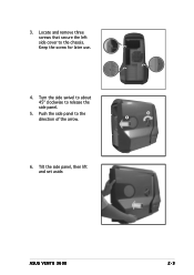
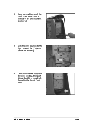
VENTO 3600 Front Panel Removal
Related Manual Pages
Similar Questions

Broken Front Panel,
Hi can i buy a repair part for my case the front movable panel have broken and come off?
Hi can i buy a repair part for my case the front movable panel have broken and come off?
(Posted by philfree61 11 years ago)