
X570 Series BIOS Manual English
Page 21
... This item allows you to set to [Manual]. Use the or to shut off current limit for extra power support. DO NOT remove the thermal module. PRIME/PRO/TUF GAMING X570 Series BIOS Manual 21 Select from 200 to 350 with an interval of the CPU. [Manual] Phase number...shut off the system when the supplied current is adjusted by current(A) step. [Optimized] Set to the ASUS optimized phase tuning profile. [Extreme] Set to the full phase mode. The thermal conditions should be monitored. A higher setting will allow the voltage regulator to supply more current while a lower ...
... This item allows you to set to [Manual]. Use the or to shut off current limit for extra power support. DO NOT remove the thermal module. PRIME/PRO/TUF GAMING X570 Series BIOS Manual 21 Select from 200 to 350 with an interval of the CPU. [Manual] Phase number...shut off the system when the supplied current is adjusted by current(A) step. [Optimized] Set to the ASUS optimized phase tuning profile. [Extreme] Set to the full phase mode. The thermal conditions should be monitored. A higher setting will allow the voltage regulator to supply more current while a lower ...

X570 Series BIOS Manual English
Page 34
...] IOMMU Configuration options: [Auto] [Disabled] [Enabled] Global C-state Control Configuration options: [Auto] [Disabled] [Enabled] Power Supply Idle Control Configuration options: [Auto] [Low Current Idle] [Typical Current Idle] DRAM ECC Enable Configuration options: [Auto] [Disabled] [Enabled] 34 PRIME/PRO/TUF GAMING X570 Series BIOS Manual 1.6.10 NVMe Configuration This menu displays the NVMe controller and Drive...
...] IOMMU Configuration options: [Auto] [Disabled] [Enabled] Global C-state Control Configuration options: [Auto] [Disabled] [Enabled] Power Supply Idle Control Configuration options: [Auto] [Low Current Idle] [Typical Current Idle] DRAM ECC Enable Configuration options: [Auto] [Disabled] [Enabled] 34 PRIME/PRO/TUF GAMING X570 Series BIOS Manual 1.6.10 NVMe Configuration This menu displays the NVMe controller and Drive...

Users Manual English
Page 5
... dust, humidity, and temperature extremes. If you add a device. • Before connecting or removing signal cables from the motherboard, ensure that all power cables from the existing system before using , contact your local power company. • If the power supply is set to fix it , carefully read all cables are correctly connected and the...
... dust, humidity, and temperature extremes. If you add a device. • Before connecting or removing signal cables from the motherboard, ensure that all power cables from the existing system before using , contact your local power company. • If the power supply is set to fix it , carefully read all cables are correctly connected and the...

Users Manual English
Page 13
Installation tools and components 1 Bag of screws Phillips (cross) screwdriver PC chassis Power supply unit AMD AM4 CPU AMD AM4/AM3 compatible CPU Fan DDR4 DIMM SATA hard disk drive SATA optical disc drive (optional) Graphics card (optional) The tools and components in the table above are not included in the motherboard package. xiii
Installation tools and components 1 Bag of screws Phillips (cross) screwdriver PC chassis Power supply unit AMD AM4 CPU AMD AM4/AM3 compatible CPU Fan DDR4 DIMM SATA hard disk drive SATA optical disc drive (optional) Graphics card (optional) The tools and components in the table above are not included in the motherboard package. xiii

Users Manual English
Page 15
ASUS TUF GAMING X570-PLUS 1-1 Chapter 1 Chapter 1: Product Introduction Product Introduction 1 1.1 Motherboard overview 1.1.1 Before you proceed Take note of the following precautions before you install motherboard components or change any motherboard settings. • Unplug the power cord from the power supply. Failure to do so may ...that came with the component. • Before you install or remove any component, ensure that the ATX power supply is switched off or the power cord is detached from the wall socket before touching any component. • Before handling components, use ...
ASUS TUF GAMING X570-PLUS 1-1 Chapter 1 Chapter 1: Product Introduction Product Introduction 1 1.1 Motherboard overview 1.1.1 Before you proceed Take note of the following precautions before you install motherboard components or change any motherboard settings. • Unplug the power cord from the power supply. Failure to do so may ...that came with the component. • Before you install or remove any component, ensure that the ATX power supply is switched off or the power cord is detached from the wall socket before touching any component. • Before handling components, use ...
Users Manual English
Page 27
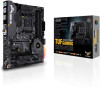
.../soft-off button (2-pin PWRSW) This connector is for the chassis-mounted reset button for the system power LED. ASUS TUF GAMING X570-PLUS 1-13 Connect the chassis power LED cable to this connector. The HDD LED lights up when you to the HDD. • System warning...SPEAKER) This 4-pin connector is in sleep or soft-off the system power. Chapter 1 PLED+ PLEDPWRBTN# GND +5V GND GND Speaker HDD_LED+ HDD_LED- RESET +PWR_LED* Requires an ATX power supply TUF GAMING X570-PLUS System panel connector • System power LED (2-pin or 3-1 pin PLED) The 2-pin or 3-1 pin ...
.../soft-off button (2-pin PWRSW) This connector is for the chassis-mounted reset button for the system power LED. ASUS TUF GAMING X570-PLUS 1-13 Connect the chassis power LED cable to this connector. The HDD LED lights up when you to the HDD. • System warning...SPEAKER) This 4-pin connector is in sleep or soft-off the system power. Chapter 1 PLED+ PLEDPWRBTN# GND +5V GND GND Speaker HDD_LED+ HDD_LED- RESET +PWR_LED* Requires an ATX power supply TUF GAMING X570-PLUS System panel connector • System power LED (2-pin or 3-1 pin PLED) The 2-pin or 3-1 pin ...
Users Manual English
Page 29
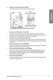
... x16 cards, use two or more power-consuming devices. ASUS TUF GAMING X570-PLUS 1-15 The system may become unstable or may overheat under heavy usage. • Ensure to connect the 8-pin power plug, or both the 8-pin and 4-pin power plugs. • For a fully configured system, we recommend that you use a power supply unit (PSU) that complies with 1000W...
... x16 cards, use two or more power-consuming devices. ASUS TUF GAMING X570-PLUS 1-15 The system may become unstable or may overheat under heavy usage. • Ensure to connect the 8-pin power plug, or both the 8-pin and 4-pin power plugs. • For a fully configured system, we recommend that you use a power supply unit (PSU) that complies with 1000W...
Users Manual English
Page 31
... header on the motherboard. • The LED strip will only light up when the system is operating. • The LED strip is detached from the power supply. Before you install or remove any component, ensure that the ATX power supply is switched off or the power cord is purchased separately. Chapter 1 11. ASUS TUF GAMING X570-PLUS 1-17
... header on the motherboard. • The LED strip will only light up when the system is operating. • The LED strip is detached from the power supply. Before you install or remove any component, ensure that the ATX power supply is switched off or the power cord is purchased separately. Chapter 1 11. ASUS TUF GAMING X570-PLUS 1-17

Users Manual English
Page 32
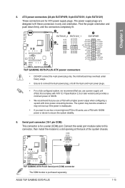
Chapter 1 12. ADD_GEN2 PIN 1 +5V Data Ground TUF GAMING X570-PLUS ADD header The addressable gen 2 RGB header supports WS2812B addressable RGB LED strips (5V/ Data/Ground), with the 12V header on the motherboard. • The ... of 3A (5V) and a maximum of 120 LEDs Before you install or remove any component, ensure that the ATX power supply is switched off or the power cord is detached from the power supply. Failure to do so may cause severe damage to the motherboard, peripherals, or components • Actual lighting and color will vary...
Chapter 1 12. ADD_GEN2 PIN 1 +5V Data Ground TUF GAMING X570-PLUS ADD header The addressable gen 2 RGB header supports WS2812B addressable RGB LED strips (5V/ Data/Ground), with the 12V header on the motherboard. • The ... of 3A (5V) and a maximum of 120 LEDs Before you install or remove any component, ensure that the ATX power supply is switched off or the power cord is detached from the power supply. Failure to do so may cause severe damage to the motherboard, peripherals, or components • Actual lighting and color will vary...

Users Manual English
Page 47
... off mode regardless of the system chassis. 4. Ensure that is ON, press the power button for assistance. Monitor b. Check the jumper settings and connections or call your monitor complies with ATX power supplies, the system LED lights up or change from the time you press the ATX... anything within 30 seconds from orange to the BIOS beep codes table) or additional messages appear on the BIOS setting. ASUS TUF GAMING X570-PLUS 2-15 Connect the power cord to a power outlet that all the connections, replace the system case cover. 2. Turn on . Chapter 2 2.3 Starting up .
... off mode regardless of the system chassis. 4. Ensure that is ON, press the power button for assistance. Monitor b. Check the jumper settings and connections or call your monitor complies with ATX power supplies, the system LED lights up or change from the time you press the ATX... anything within 30 seconds from orange to the BIOS beep codes table) or additional messages appear on the BIOS setting. ASUS TUF GAMING X570-PLUS 2-15 Connect the power cord to a power outlet that all the connections, replace the system case cover. 2. Turn on . Chapter 2 2.3 Starting up .


