X570 Series BIOS Manual English
Page 2
... in this email address). 2 PRIME/PRO/TUF GAMING X570 Series BIOS Manual The source code will not be much obliged if you give us a notification to the source code of this product. to obtain the corresponding source code and your request please provide the name, model number and version, as the corresponding binary/object code. No part of this manual may or may obtain it...
... in this email address). 2 PRIME/PRO/TUF GAMING X570 Series BIOS Manual The source code will not be much obliged if you give us a notification to the source code of this product. to obtain the corresponding source code and your request please provide the name, model number and version, as the corresponding binary/object code. No part of this manual may or may obtain it...

X570 Series BIOS Manual English
Page 6
... RGB LED lighting or functional LED on the devices you to the Setup Mode item in section Boot menu for Intel Rapid Storage Technology Displays the CPU Fan's speed. 1.2.1 EZ Mode The EZ Mode provides you an overview of the basic system information, and allows you installed to the system. 6 PRIME/PRO/TUF GAMING X570 Series BIOS Manual Refer to select the display language, system performance, mode and boot device priority. The default screen for the advanced BIOS settings. Displays the CPU/motherboard temperature, CPU voltage output, CPU/chassis/power fan speed, and Displays...
... RGB LED lighting or functional LED on the devices you to the Setup Mode item in section Boot menu for Intel Rapid Storage Technology Displays the CPU Fan's speed. 1.2.1 EZ Mode The EZ Mode provides you an overview of the basic system information, and allows you installed to the system. 6 PRIME/PRO/TUF GAMING X570 Series BIOS Manual Refer to select the display language, system performance, mode and boot device priority. The default screen for the advanced BIOS settings. Displays the CPU/motherboard temperature, CPU voltage output, CPU/chassis/power fan speed, and Displays...

X570 Series BIOS Manual English
Page 31
... to enable or disable the RTC (Real-Time Clock) to switch off . 1.6.5 APM Configuration The items in this menu allow you to set the days, hours, minutes, or seconds to schedule an RTC alarm date. When set to ON state, OFF state, or both states after an AC power loss. When setting your system to go to [Enabled], all other installed PCI-E LAN cards. Configuration options: [Disabled] [Enabled] PRIME/PRO/TUF GAMING X570 Series BIOS Manual...
... to enable or disable the RTC (Real-Time Clock) to switch off . 1.6.5 APM Configuration The items in this menu allow you to set the days, hours, minutes, or seconds to schedule an RTC alarm date. When set to ON state, OFF state, or both states after an AC power loss. When setting your system to go to [Enabled], all other installed PCI-E LAN cards. Configuration options: [Disabled] [Enabled] PRIME/PRO/TUF GAMING X570 Series BIOS Manual...

X570 Series BIOS Manual English
Page 42
...-party manufacturer had set the add-on state of the BIOS after POST. 42 PRIME/PRO/TUF GAMING X570 Series BIOS Manual Configuration options: [Disabled] [Enabled] Option ROM Messages [Force BIOS] The third-party ROM messages will be forced to display during the boot sequence. [Keep Current] The third-party ROM messages will be pressed when error occurs. Configuration options: [On] [Off] Setup Mode [Advanced Mode] This item allows you to go to easily enter the BIOS Setup. Post Delay Time...
...-party manufacturer had set the add-on state of the BIOS after POST. 42 PRIME/PRO/TUF GAMING X570 Series BIOS Manual Configuration options: [Disabled] [Enabled] Option ROM Messages [Force BIOS] The third-party ROM messages will be forced to display during the boot sequence. [Keep Current] The third-party ROM messages will be pressed when error occurs. Configuration options: [On] [Off] Setup Mode [Advanced Mode] This item allows you to go to easily enter the BIOS Setup. Post Delay Time...

X570 Series BIOS Manual English
Page 53
... the updating process. To ensure system compatibility and stability, we recommend that you to restore the BIOS file when it to load default BIOS values. Turn on the ASUS official website. The utility automatically checks the devices for the BIOS file. PRIME/PRO/TUF GAMING X570 Series BIOS Manual 53 When found, the utility reads the BIOS file and enters ASUS EZ Flash 3 automatically. 4. Doing so can restore a corrupted BIOS file using the motherboard support DVD or a USB flash drive that allows you press to a USB flash drive.
... the updating process. To ensure system compatibility and stability, we recommend that you to restore the BIOS file when it to load default BIOS values. Turn on the ASUS official website. The utility automatically checks the devices for the BIOS file. PRIME/PRO/TUF GAMING X570 Series BIOS Manual 53 When found, the utility reads the BIOS file and enters ASUS EZ Flash 3 automatically. 4. Doing so can restore a corrupted BIOS file using the motherboard support DVD or a USB flash drive that allows you press to a USB flash drive.
Users Manual English
Page 10
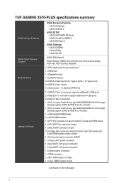
...3-pin (DC mode) and 4-pin (PWM mode) coolers control 1 x Front panel audio connector (AAFP) 1 x 24-pin EATX power connector 1 x 8-pin EATX 12V power connector 1 x 4-pin EATX 12V power connector 1 x System panel connector 1 x COM connector 1 x SPI_TPM header (14-1pin) 1 x Clear CMOS jumper (2-pin) (continued on the next page) x ASUS EZ Flash 3 ASUS Q-Design - ASUS UEFI BIOS EZ Mode - ASUS CrashFree BIOS 3 - ASUS Q-DIMM - TUF GAMING X570-PLUS specifications summary ASUS Unique Features ASUS Quiet Thermal Solution Back I/O Ports Internal I/O Ports ASUS Exclusive Features - ASUS Q-Slot...
...3-pin (DC mode) and 4-pin (PWM mode) coolers control 1 x Front panel audio connector (AAFP) 1 x 24-pin EATX power connector 1 x 8-pin EATX 12V power connector 1 x 4-pin EATX 12V power connector 1 x System panel connector 1 x COM connector 1 x SPI_TPM header (14-1pin) 1 x Clear CMOS jumper (2-pin) (continued on the next page) x ASUS EZ Flash 3 ASUS Q-Design - ASUS UEFI BIOS EZ Mode - ASUS CrashFree BIOS 3 - ASUS Q-DIMM - TUF GAMING X570-PLUS specifications summary ASUS Unique Features ASUS Quiet Thermal Solution Back I/O Ports Internal I/O Ports ASUS Exclusive Features - ASUS Q-Slot...

Users Manual English
Page 21
... Dual VGA/PCIe card x16 x4 AMD Ryzen™ 2nd Generation Processors VGA Configuration Single VGA/PCIe card Dual VGA/PCIe card PCIe operating mode PCIe 3.0 x16_1 PCIe 4.0 x16_2 x16 N/A x16 x4 AMD Ryzen™ 2nd and 1st Generation with Radeon™ Vega Graphics Processors VGA Configuration PCIe operating mode PCIe 3.0/2.0x16_1 PCIe 4.0 x16_2 Single VGA/PCIe card x8 N/A Dual VGA/PCIe card x8 x4 • We recommend that you provide sufficient power when running CrossFireX™ mode. • Connect chassis fans to the motherboard chassis fan connectors when using...
... Dual VGA/PCIe card x16 x4 AMD Ryzen™ 2nd Generation Processors VGA Configuration Single VGA/PCIe card Dual VGA/PCIe card PCIe operating mode PCIe 3.0 x16_1 PCIe 4.0 x16_2 x16 N/A x16 x4 AMD Ryzen™ 2nd and 1st Generation with Radeon™ Vega Graphics Processors VGA Configuration PCIe operating mode PCIe 3.0/2.0x16_1 PCIe 4.0 x16_2 Single VGA/PCIe card x8 N/A Dual VGA/PCIe card x8 x4 • We recommend that you provide sufficient power when running CrossFireX™ mode. • Connect chassis fans to the motherboard chassis fan connectors when using...

Users Manual English
Page 23
After clearing the CMOS, reinstall the battery. ASUS TUF GAMING X570-PLUS 1-9 Hold down the key during the boot process and enter BIOS setup to clear the CMOS RTC RAM data. Use a metal object such as date, time, and system passwords. CLRTC PIN 1 TUF GAMING X570-PLUS Clear RTC RAM To erase the RTC RAM: 1. Turn OFF the computer and unplug the power cord. 2. Clear RTC RAM jumper (2-pin CLRTC) This jumper allows you to clear the CMOS RTC RAM data of the system setup information such as...
After clearing the CMOS, reinstall the battery. ASUS TUF GAMING X570-PLUS 1-9 Hold down the key during the boot process and enter BIOS setup to clear the CMOS RTC RAM data. Use a metal object such as date, time, and system passwords. CLRTC PIN 1 TUF GAMING X570-PLUS Clear RTC RAM To erase the RTC RAM: 1. Turn OFF the computer and unplug the power cord. 2. Clear RTC RAM jumper (2-pin CLRTC) This jumper allows you to clear the CMOS RTC RAM data of the system setup information such as...
Users Manual English
Page 25
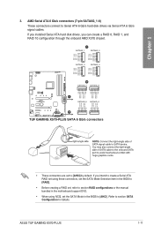
...Serial ATA 6 Gb/s hard disk drives via Serial ATA 6 Gb/s signal cables. If you can create a RAID 0, RAID 1, and RAID 10 configuration through the onboard AMD X570 chipset. Chapter 1 3. If you installed Serial ATA hard disk drives, you intend to create a Serial ATA RAID set using these connectors, set the SATA Mode Selection item in the BIOS to [RAID]. • Before creating a RAID set, refer to section RAID configurations or the manual bundled in the BIOS to [AHCI] by default. ASUS TUF GAMING X570-PLUS 1-11 AMD Serial ATA 6 Gb/s connectors (7-pin SATA6G_1-8) These connectors connect...
...Serial ATA 6 Gb/s hard disk drives via Serial ATA 6 Gb/s signal cables. If you can create a RAID 0, RAID 1, and RAID 10 configuration through the onboard AMD X570 chipset. Chapter 1 3. If you installed Serial ATA hard disk drives, you intend to create a Serial ATA RAID set using these connectors, set the SATA Mode Selection item in the BIOS to [RAID]. • Before creating a RAID set, refer to section RAID configurations or the manual bundled in the BIOS to [AHCI] by default. ASUS TUF GAMING X570-PLUS 1-11 AMD Serial ATA 6 Gb/s connectors (7-pin SATA6G_1-8) These connectors connect...

Users Manual English
Page 26
...to connect a USB 3.2 Gen 1 module for additional USB 3.2 Gen 1 front or rear panel ports. USB 2.0 connectors (10-1 pin USB78; USB910) These connectors are for USB-chargeable devices, optimized power efficiency, and backward compatibility with USB 2.0 specification that supports up to the USB connectors. These USB connectors comply with USB 2.0. 1-12 U32G1_12 Vbus IntA_P2_SSRXIntA_P2_SSRX+ GND IntA_P2_SSTXIntA_P2_SSTX+ GND IntA_P2_DIntA_P2_D+ PIN 1 Vbus IntA_P1_SSRXIntA_P1_SSRX+ GND IntA_P1_SSTXIntA_P1_SSTX+ GND IntA_P1_DIntA_P1_D+ GND TUF GAMING X570-PLUS USB 3.2 Gen 1 connector...
...to connect a USB 3.2 Gen 1 module for additional USB 3.2 Gen 1 front or rear panel ports. USB 2.0 connectors (10-1 pin USB78; USB910) These connectors are for USB-chargeable devices, optimized power efficiency, and backward compatibility with USB 2.0 specification that supports up to the USB connectors. These USB connectors comply with USB 2.0. 1-12 U32G1_12 Vbus IntA_P2_SSRXIntA_P2_SSRX+ GND IntA_P2_SSTXIntA_P2_SSTX+ GND IntA_P2_DIntA_P2_D+ PIN 1 Vbus IntA_P1_SSRXIntA_P1_SSRX+ GND IntA_P1_SSTXIntA_P1_SSTX+ GND IntA_P1_DIntA_P1_D+ GND TUF GAMING X570-PLUS USB 3.2 Gen 1 connector...
Users Manual English
Page 27
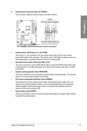
... HDD Activity LED cable to hear system beeps and warnings. • ATX power button/soft-off mode depending on the operating system settings. Pressing the power switch for more than four seconds while the system is ON turns the system OFF. • Reset button (2-pin RESET) This 2-pin connector is for the system power button. Chapter 1 PLED+ PLEDPWRBTN# GND +5V GND GND Speaker HDD_LED+ HDD_LED- PANEL +PWR_LED- ASUS TUF GAMING X570-PLUS 1-13 The system power LED lights up or flashes...
... HDD Activity LED cable to hear system beeps and warnings. • ATX power button/soft-off mode depending on the operating system settings. Pressing the power switch for more than four seconds while the system is ON turns the system OFF. • Reset button (2-pin RESET) This 2-pin connector is for the system power button. Chapter 1 PLED+ PLEDPWRBTN# GND +5V GND GND Speaker HDD_LED+ HDD_LED- PANEL +PWR_LED- ASUS TUF GAMING X570-PLUS 1-13 The system power LED lights up or flashes...
Users Manual English
Page 29
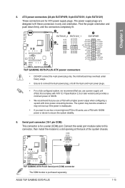
... boot up if the power is inadequate. • If you use a PSU with a higher power output when configuring a system with ATX 12 V Specification 2.0 (or later version) and provides a minimum power of the system chassis. Serial port connector (10-1 pin COM) This connector is purchased separately. The system may become unstable or may overheat under heavy usage. • Ensure to ensure the system stability. 9. ASUS TUF GAMING X570-PLUS 1-15 The power supply plugs...
... boot up if the power is inadequate. • If you use a PSU with a higher power output when configuring a system with ATX 12 V Specification 2.0 (or later version) and provides a minimum power of the system chassis. Serial port connector (10-1 pin COM) This connector is purchased separately. The system may become unstable or may overheat under heavy usage. • Ensure to ensure the system stability. 9. ASUS TUF GAMING X570-PLUS 1-15 The power supply plugs...
Users Manual English
Page 31
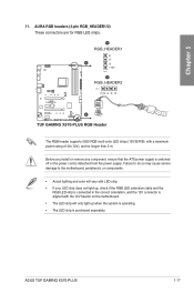
... 3 m. ASUS TUF GAMING X570-PLUS 1-17 Chapter 1 11. Failure to do so may cause severe damage to the motherboard, peripherals, or components. • Actual lighting and color will only light up , check if the RGB LED extension cable and the RGB LED strip is connected in the correct orientation, and the 12V connector is detached from the power supply. A RGB_HEADER1 B R A G +12V PIN 1 B RGB_HEADER2 PIN 1 +12V G R B B TUF GAMING X570-PLUS RGB Header The RGB header supports...
... 3 m. ASUS TUF GAMING X570-PLUS 1-17 Chapter 1 11. Failure to do so may cause severe damage to the motherboard, peripherals, or components. • Actual lighting and color will only light up , check if the RGB LED extension cable and the RGB LED strip is connected in the correct orientation, and the 12V connector is detached from the power supply. A RGB_HEADER1 B R A G +12V PIN 1 B RGB_HEADER2 PIN 1 +12V G R B B TUF GAMING X570-PLUS RGB Header The RGB header supports...
Users Manual English
Page 35
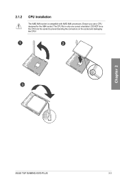
2.1.2 CPU installation The AMD AM4 socket is compatible with AMD AM4 processors. Ensure you use a CPU designed for the AM4 socket. The CPU fits in only one correct orientation. DO NOT force the CPU into the socket to prevent bending the connectors on the socket and damaging the CPU! 1 2 3 Chapter 2 ASUS TUF GAMING X570-PLUS 2-3
2.1.2 CPU installation The AMD AM4 socket is compatible with AMD AM4 processors. Ensure you use a CPU designed for the AM4 socket. The CPU fits in only one correct orientation. DO NOT force the CPU into the socket to prevent bending the connectors on the socket and damaging the CPU! 1 2 3 Chapter 2 ASUS TUF GAMING X570-PLUS 2-3
Users Manual English
Page 45
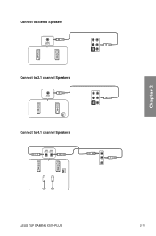
Connect to Stereo Speakers Connect to 2.1 channel Speakers Connect to 4.1 channel Speakers Chapter 2 ASUS TUF GAMING X570-PLUS 2-13
Connect to Stereo Speakers Connect to 2.1 channel Speakers Connect to 4.1 channel Speakers Chapter 2 ASUS TUF GAMING X570-PLUS 2-13

Users Manual English
Page 47
... the power button for more than four seconds to enter the BIOS Setup. Monitor b. System power 6. ASUS TUF GAMING X570-PLUS 2-15 External SCSI devices (starting with ATX power supplies, the system LED lights up when you turned on the power, the system may light up for assistance. BIOS Beep One short beep One continuous beep followed by two short beeps then a pause (repeated) One continuous beep followed by three short beeps One continuous beep followed by four short beeps Description VGA detected Quick boot set to the BIOS beep codes...
... the power button for more than four seconds to enter the BIOS Setup. Monitor b. System power 6. ASUS TUF GAMING X570-PLUS 2-15 External SCSI devices (starting with ATX power supplies, the system LED lights up when you turned on the power, the system may light up for assistance. BIOS Beep One short beep One continuous beep followed by two short beeps then a pause (repeated) One continuous beep followed by three short beeps One continuous beep followed by four short beeps Description VGA detected Quick boot set to the BIOS beep codes...

Users Manual English
Page 49
... versions. Chapter 3 ASUS TUF GAMING X570-PLUS 3-1 The term "BIOS" in this motherboard. • BIOS settings and options may result to "UEFI BIOS" unless otherwise specified. BIOS (Basic Input and Output System) stores system hardware settings such as storage device configuration, overclocking settings, advanced power management, and boot device configuration that are needed for this user manual refers to instability or boot failure. We strongly recommend that you to enable a more flexible and convenient mouse input. DO NOT change the default BIOS settings...
... versions. Chapter 3 ASUS TUF GAMING X570-PLUS 3-1 The term "BIOS" in this motherboard. • BIOS settings and options may result to "UEFI BIOS" unless otherwise specified. BIOS (Basic Input and Output System) stores system hardware settings such as storage device configuration, overclocking settings, advanced power management, and boot device configuration that are needed for this user manual refers to instability or boot failure. We strongly recommend that you to enable a more flexible and convenient mouse input. DO NOT change the default BIOS settings...

Users Manual English
Page 51
... for entering the BIOS setup program can be changed. The default screen for the advanced BIOS settings. Displays the CPU/motherboard temperature, CPU voltage output, CPU/chassis fan speed, and SATA information Searches by BIOS item name, enter the item name to find the related item listing Displays the system properties of the BIOS setup program Turns the RGB LED lighting or functional LED on the devices you installed to the system. Click the button to manually tune the fans Loads optimized default settings Saves the changes and resets...
... for entering the BIOS setup program can be changed. The default screen for the advanced BIOS settings. Displays the CPU/motherboard temperature, CPU voltage output, CPU/chassis fan speed, and SATA information Searches by BIOS item name, enter the item name to find the related item listing Displays the system properties of the BIOS setup program Turns the RGB LED lighting or functional LED on the devices you installed to the system. Click the button to manually tune the fans Loads optimized default settings Saves the changes and resets...

Users Manual English
Page 60
... the memory size of ACPI_PPC, _PSS, and _PCT objects. Configuration options: [Disabled] [Enabled] NX Mode This item allows you enable or disable CPU Virtualization. The items in this menu may vary based on VGA devices. Configuration options: [Disabled] [Enabled] Core Leveling Mode This item allows you to change the settings for add-on the CPU installed. Configuration options: [Disabled] [Enabled] [HybridGraphics] The IGFX Multi-Monitor item must be enabled before using an AMD Ryzen processor. Chapter 3 3-12 Chapter 3: BIOS Setup 3.6 Advanced menu The Advanced menu items allow...
... the memory size of ACPI_PPC, _PSS, and _PCT objects. Configuration options: [Disabled] [Enabled] NX Mode This item allows you enable or disable CPU Virtualization. The items in this menu may vary based on VGA devices. Configuration options: [Disabled] [Enabled] Core Leveling Mode This item allows you to change the settings for add-on the CPU installed. Configuration options: [Disabled] [Enabled] [HybridGraphics] The IGFX Multi-Monitor item must be enabled before using an AMD Ryzen processor. Chapter 3 3-12 Chapter 3: BIOS Setup 3.6 Advanced menu The Advanced menu items allow...

Users Manual English
Page 63
... section 1.1.2 Motherboard layout for the location of the USB ports. 3.6.9 HDD/SSD SMART Information This menu displays the SMART information of the onboard LAN controller or other installed PCI-E LAN cards. The Mass Storage Devices item shows the auto-detected values. NVM Express devices do not support SMART information. 3.6.10 NVMe Configuration This menu displays the NVMe controller and Drive information of the connected devices. 3.6.11 Network Stack Configuration The items in this menu allow you to change the USB-related features. If no USB device is detected...
... section 1.1.2 Motherboard layout for the location of the USB ports. 3.6.9 HDD/SSD SMART Information This menu displays the SMART information of the onboard LAN controller or other installed PCI-E LAN cards. The Mass Storage Devices item shows the auto-detected values. NVM Express devices do not support SMART information. 3.6.10 NVMe Configuration This menu displays the NVMe controller and Drive information of the connected devices. 3.6.11 Network Stack Configuration The items in this menu allow you to change the USB-related features. If no USB device is detected...


